Infiniti EX35. Manual - part 915


  Index      Infiniti     Infiniti EX35 - service repair manual 2008 year


Search            


Content   ..  913  914  915  916   ..


Infiniti EX35. Manual - part 915


HAC-56

< FUNCTION DIAGNOSIS >

[AUTOMATIC AIR CONDITIONER]

MAGNET CLUTCH CONTROL SYSTEM

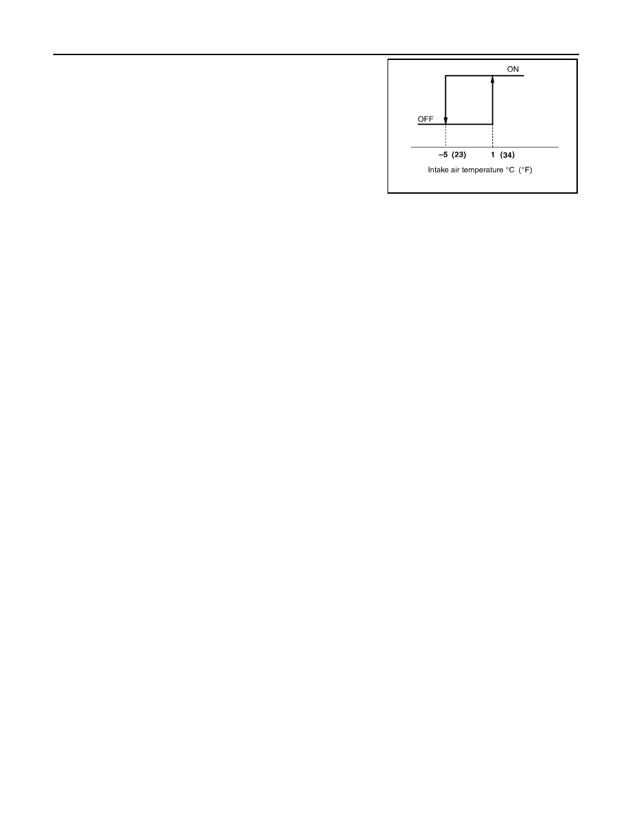
When intake air temperature is higher than 1

°

C (34

°

F), the compres-

sor turns ON. The compressor turns OFF when intake air tempera-
ture is lower than 

5

°

C (23

°

F).

SJIA0267E

DIAGNOSIS SYSTEM (UNIFIED METER & A/C AMP.)

HAC-57

< FUNCTION DIAGNOSIS >

[AUTOMATIC AIR CONDITIONER]

C

D

E

F

G

H

J

K

L

M

A

B

HAC

N

O

P

DIAGNOSIS SYSTEM (UNIFIED METER & A/C AMP.)

WITHOUT LEFT AND RIGHT VENTILATION TEMPERATURE SEPARATELY
CONTROL SYSTEM

WITHOUT LEFT AND RIGHT VENTILATION TEMPERATURE SEPARATELY CON-
TROL SYSTEM : Diagnosis Description

INFOID:0000000003545585

SELF-DIAGNOSIS SYSTEM

The self-diagnosis system is built into the unified meter and A/C amp. to quickly locate the cause of malfunc-
tions.

SELF-DIAGNOSIS FUNCTION

• The self-diagnosis system diagnoses sensors, door motors, blower motor, etc. by system line. Refer to appli-

cable sections (items) for details. Shifting from normal control to the self-diagnosis system is accomplished
by starting the engine (turning the ignition switch ON) and pressing OFF switch for at least 5 seconds. The
OFF switch must be pressed within 10 seconds after starting the engine (ignition switch is turned ON). This
system is canceled by either pressing AUTO switch or turning the ignition switch OFF. Shifting from one step
is accomplished by means of turning temperature control dial, as required.

• Shifting from STEP-5 to AUXILIARY MECHANISM is accomplished by means of turning fan control dial

clockwise.

- Temperature setting trimmer. Refer to 

HAC-8, "WITHOUT LEFT AND RIGHT VENTILATION TEMPERA-

TURE SEPARATELY CONTROL SYSTEM : Temperature Setting Trimmer"

.

- Foot position setting trimmer. Refer to 

HAC-9, "WITHOUT LEFT AND RIGHT VENTILATION TEMPERA-

TURE SEPARATELY CONTROL SYSTEM : Foot Position Setting Trimmer"

.

HAC-58

< FUNCTION DIAGNOSIS >

[AUTOMATIC AIR CONDITIONER]

DIAGNOSIS SYSTEM (UNIFIED METER & A/C AMP.)

- Inlet port memory function. Refer to 

HAC-10, "WITHOUT LEFT AND RIGHT VENTILATION TEMPERA-

TURE SEPARATELY CONTROL SYSTEM : Inlet Port Memory Function"

.

CONFORMATION METHOD

1.

SET IN SELF-DIAGNOSIS MODE

1.

Turn ignition switch ON.

2.

Set in self-diagnosis mode as per the following. Press OFF switch for at least 5 seconds within 10 sec-
onds after starting engine (ignition switch is turned ON).

NOTE:
• If battery voltage drops below 12 V during diagnosis STEP-3, door motor speed becomes slower and as a

result, the system may generate an error even when operation is normal. Start engine before performing this
diagnosis to avoid this.

• Former STEP-1 (indicators and display screen are checked) does not exist in this self-diagnosis function.
• OFF switch may not be recognized according to the timing of pressing it. Operate OFF switch after turning

the intake switch indicators (REC/FRE) ON.

>> GO TO 2.

2.

STEP-2: SENSOR AND DOOR MOTOR CIRCUITS ARE CHECKED FOR OPEN OR SHORT CIRCUIT

JSIIA0770GB

DIAGNOSIS SYSTEM (UNIFIED METER & A/C AMP.)

HAC-59

< FUNCTION DIAGNOSIS >

[AUTOMATIC AIR CONDITIONER]

C

D

E

F

G

H

J

K

L

M

A

B

HAC

N

O

P

Does code No. 20 appear on the display?

YES

>> GO TO 3.

NO

>> GO TO 11.

3.

STEP-3: MODE DOOR AND INTAKE DOOR POSITIONS ARE CHECKED

Turn temperature control dial clockwise.

Does code No. 30 appear on the display?

YES

>> GO TO 4.

NO

>> GO TO 12.

4.

STEP-4: OPERATION OF EACH DOOR MOTOR IS CHECKED

1.

Turn temperature control dial clockwise.

2.

Press DEF (

) switch. Code No. of each door motor test is

indicated on the display.

>> GO TO 5.

5.

CHECK ACTUATORS

Refer to the following chart and check discharge air flow, air temperature, blower motor duty ratio and com-
pressor operation.

Checks must be made visually, by listening the sound, or by touching air outlets with hand, etc. for improper
operation.

SJIA1778E

SJIA1779E

SJIA1780E

Code  No.

41

42

43

44

45

46

Mode door position

VENT

B/L 1

B/L 2

FOOT

D/F

DEF

Intake door position

REC

REC

20% FRE

FRE

FRE

FRE

Air mix door position

FULL COOL

FULL COOL

FULL HOT

FULL HOT

FULL HOT

FULL HOT

Blower motor duty ratio

37%

91%

65%

65%

65%

91%

Compressor (Magnet 
clutch)

ON

ON

OFF

OFF

ON

ON

Electronic control valve 
(ECV) duty ratio

100%

100%

0%

0%

50%

100%


Content   ..  913  914  915  916   ..