Infiniti EX35. Manual - part 847
FAX-18
< ON-VEHICLE REPAIR >
[AWD]
FRONT DRIVE SHAFT BOOT
FRONT DRIVE SHAFT BOOT
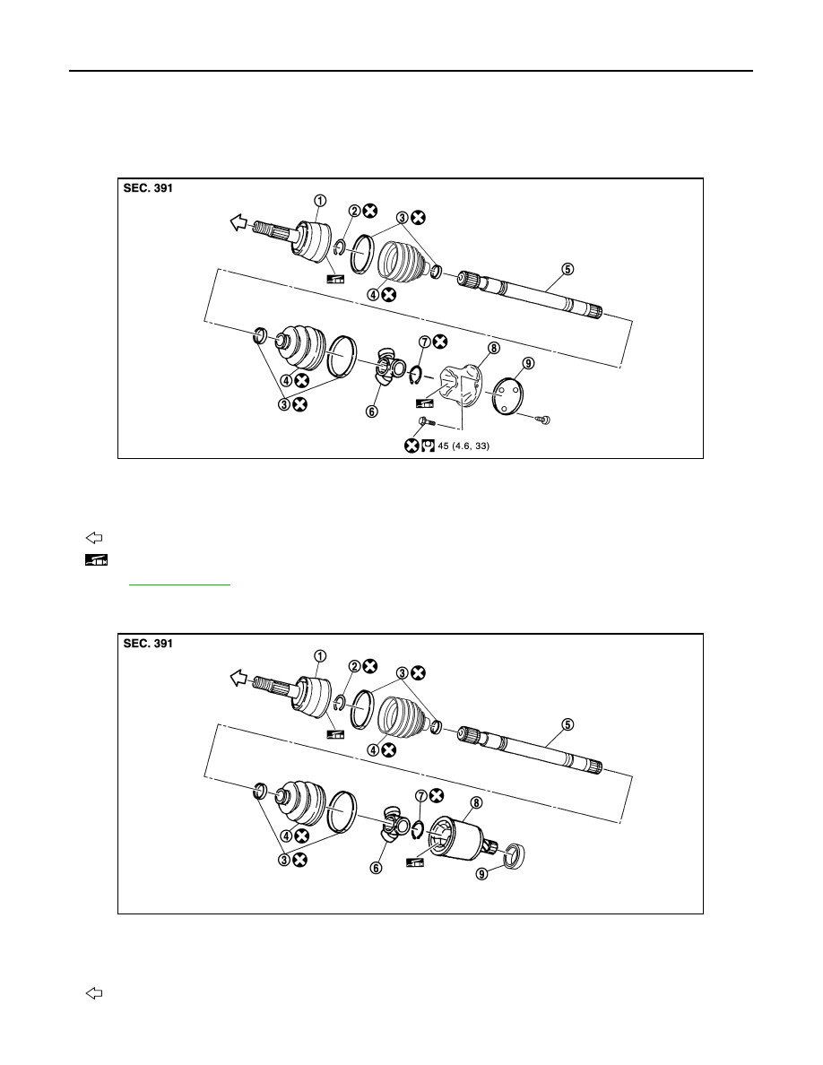
Exploded View
INFOID:0000000003138941
LEFT SIDE
RIGHT SIDE
1.
Joint sub-assembly
2.
Circular clip
3.
Boot band
4.
Boot
5.
Shaft
6.
Spider assembly
7.
Snap ring
8.
Housing
9.
Plug
: Wheel side
: NISSAN genuine grease or an equivalent.
for symbols not described on the above.
JPDIF0168GB
1.
Joint sub-assembly
2.
Circular clip
3.
Boot band
4.
Boot
5.
Shaft
6.
Spider assembly
7.
Snap ring
8.
Housing
9.
Dust shield
: Wheel side
JPDIF0169ZZ