Infiniti EX35. Manual - part 795
EXL-224
< FUNCTION DIAGNOSIS >
[HALOGEN TYPE]
TURN SIGNAL AND HAZARD WARNING LAMP SYSTEM
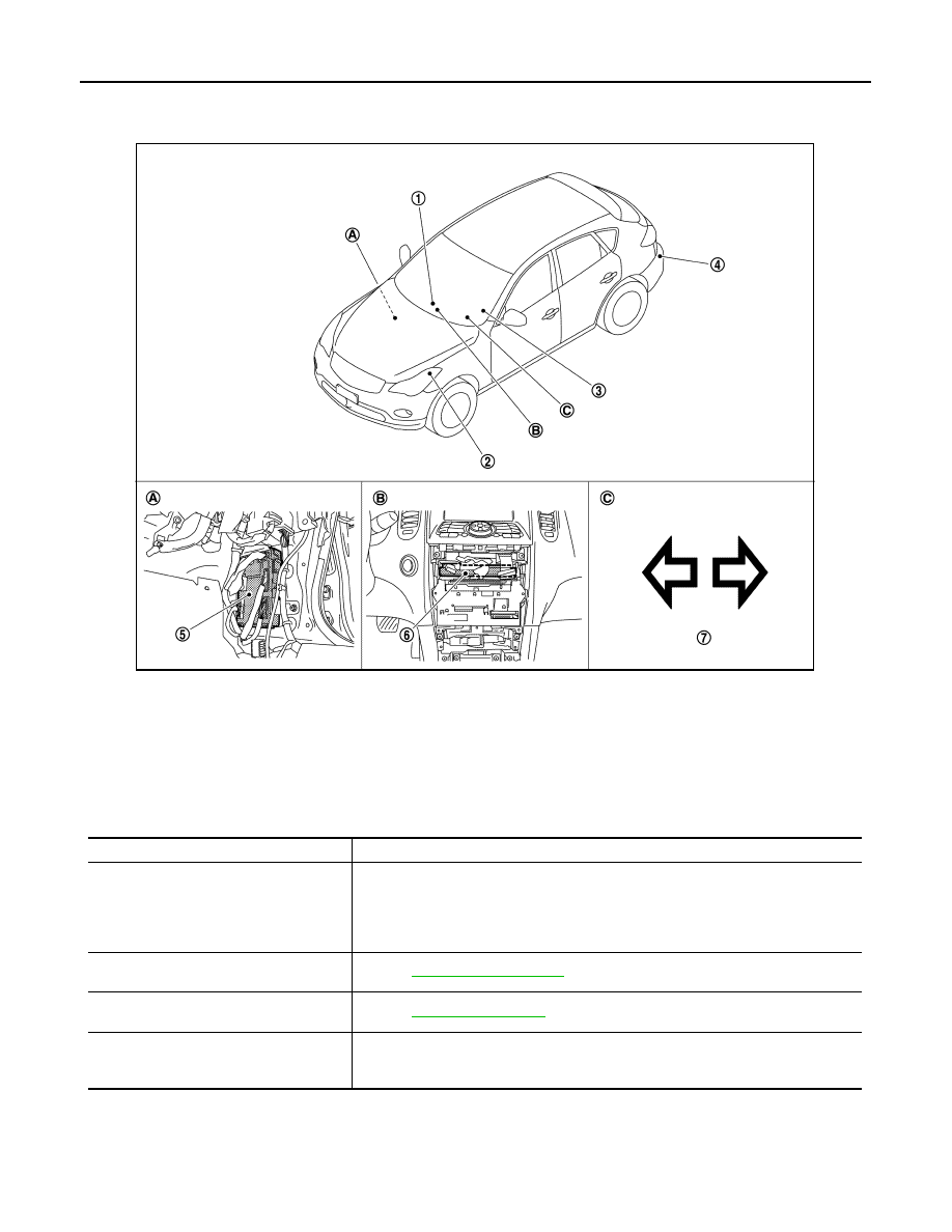
Component Parts Location
INFOID:0000000003756968
Component Description
INFOID:0000000003756969
1.
Hazard warning switch
2.
Front turn signal lamp
3.
Combination switch
4.
Rear turn signal lamp
5.
BCM
6.
Unified meter and A/C amp.
7.
Turn signal indicator lamp
A.
Dash side lower (Passenger side)
B.
Behind the cluster lid C
C.
On the combination meter
JPLIA0946ZZ
Part
Description
BCM
• Judges each switch condition by the combination switch reading function.
• Judges the blinks of the turn signal lamp and the hazard warning lamp from each
switch status. The applicable turn signal lamp blinks.
Requests the turn signal indicator lamp blink to the combination meter (with CAN
communication).
Combination switch
(Lighting & turn signal switch)
.
Hazard switch
(Multifunction switch)
Combination meter
(Turn signal indicator lamp & buzzer)
Blinks the turn signal indicator lamp and outputs the turn signal operating sound with
integrated buzzer according to the request from BCM [with CAN communication
(through unified meter and A/C amp.)].