Infiniti EX35. Manual - part 760
EXL-84
< COMPONENT DIAGNOSIS >
[XENON TYPE]
HAZARD SWITCH
HAZARD SWITCH
Description
INFOID:0000000003135350
Hazard switch is integrated in the multifunction switch. Hazard switch inputs the signals to BCM when press-
ing the switch.
Component Function Check
INFOID:0000000003135351
1.
CHECK HAZARD SWITCH SIGNAL BY CONSULT-III
CONSULT-III DATA MONITOR
1.
Turn the ignition switch ON.
2.
Select "HAZARD SW" of BCM (FLASHER) data monitor item.
3.
With operating the hazard switch, check the monitor status.
Is the item status normal?
YES
>> Hazard switch circuit is normal.
NO
>> Refer to
.
Diagnosis Procedure
INFOID:0000000003135352
1.
CHECK HAZARD SWITCH SIGNAL INPUT
With operating the hazard switch, check the voltage between the BCM harness connector and the ground.
Is the measurement value normal?
YES
>> Replace BCM.
NO
>> GO TO 2.
2.
CHECK HAZARD SWITCH SIGNAL OPEN CIRCUIT
1.
Turn the ignition switch OFF.
2.
Disconnect the multifunction switch connector and BCM connector.
3.
Check continuity between the multifunction switch harness connector and the BCM harness connector.
Monitor item
Condition
Monitor status
HAZARD SW
Hazard switch
While pressing the
switch
On
While not pressing
the switch
Off
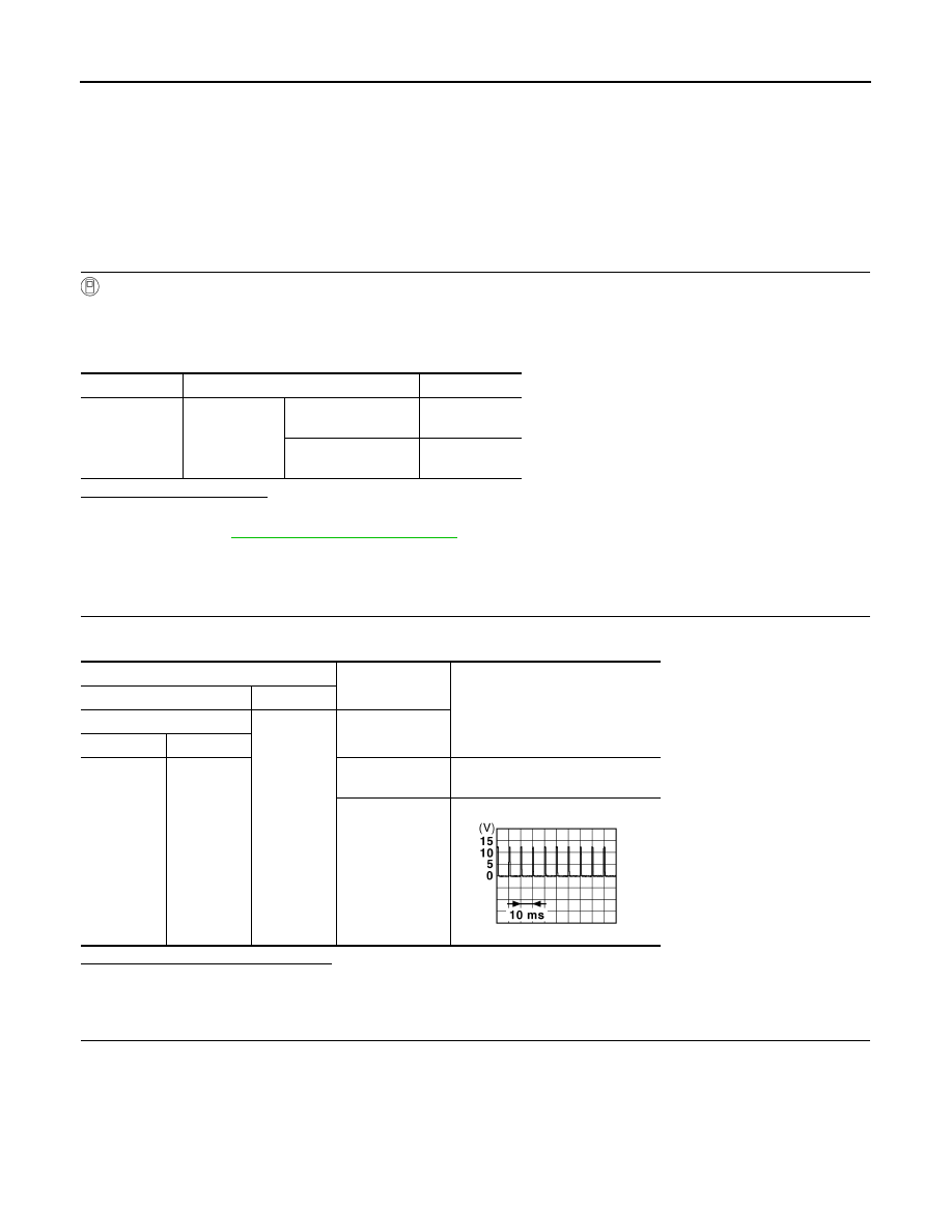
Terminals
Condition
Voltage (Approx.)
(+)
(
−
)
BCM
Ground
Hazard switch
Connector
Terminal
M122
110
While pressing
the switch
0 V
While not press-
ing the switch
JPMIA0012GB