Infiniti EX35. Manual - part 732
CYLINDER BLOCK
EM-127
< DISASSEMBLY AND ASSEMBLY >
C
D
E
F
G
H
I
J
K
L
M
A
EM
N
P
O
Factory installed parts grading:
• Service parts apply only to grade “0”.
Unit: mm (in)
*: After installing in connecting rod
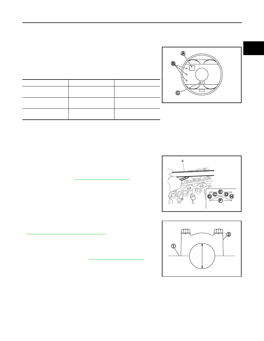
CYLINDER BLOCK DISTORTION
• Using a scraper, remove gasket on the cylinder block surface, and also remove engine oil, scale, carbon, or
other contamination.
CAUTION:
Be careful not to allow gasket flakes to enter engine oil or engine coolant passages.
• Measure the distortion on the cylinder block upper face at some
different points in six directions (C, D, E, F, G, and H) with a
straightedge (A) and a feeler gauge (B).
• If it exceeds the limit, replace cylinder block.
MAIN BEARING HOUSING INNER DIAMETER
• Install lower cylinder block (2) without installing main bearings, and
tighten lower cylinder block bolts to the specified torque. Refer to
EM-115, "Disassembly and Assembly"
for the tightening proce-
dure.
• Measure the inner diameter of main bearing housing with a bore
gauge.
• If out of the standard, replace cylinder block (1) and lower cylinder
block as assembly.
NOTE:
Cylinder block cannot be replaced as a single part, because it is
machined together with lower cylinder block.
PISTON TO CYLINDER BORE CLEARANCE
Cylinder Bore inner Diameter
H
: Front mark
I
: Management code
A
: Piston grade number
B
: Front mark
C
: Piston pin grade number
Grade
0
1
Connecting rod bushing
inner diameter *
22.000 - 22.006
(0.8661 - 0.8664)
22.006 - 22.012
(0.8664 - 0.8666)
Piston pin hole diameter
21.993 - 21.999
(0.8659 - 0.8661)
21.999 - 22. 005
(0.8661 - 0.8663)
Piston pin outer diameter
21.989 - 21.995
(0.8657 - 0.8659)
21.995 - 22.001
(0.8659 - 0.8662)
JPBIA0267ZZ
Limit
: Refer to
JPBIA0224ZZ
Standard
: Refer to
.
JPBIA0225ZZ