Infiniti EX35. Manual - part 731


  Index      Infiniti     Infiniti EX35 - service repair manual 2008 year


Search            


Content   ..  729  730  731  732   ..


Infiniti EX35. Manual - part 731


CYLINDER BLOCK

EM-123

< DISASSEMBLY AND ASSEMBLY >

C

D

E

F

G

H

I

J

K

L

M

A

EM

N

P

O

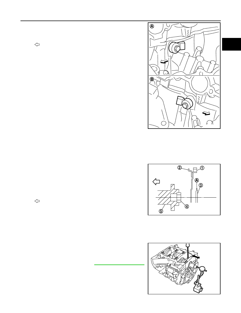
18. Install knock sensors.

• Install knock sensor so that connector faces rear of the

engine.

• After installing knock sensor, connect harness connector, and

lay it out to rear of the engine.

CAUTION:

• Never tighten mounting bolts while holding connector.   
• If any impact by dropping is applied to knock sensor,

replace it with new one.

NOTE:
• Check that there is no foreign material on the cylinder block

mating surface and the back surface of knock sensor. 

• Check that knock sensor does not interfere with other parts.

19. Note the following, assemble in the reverse order of disassembly after this step.

Drive plate

• When installing drive plate to crankshaft, be sure to correctly align crankshaft side dowel pin and drive

plate side dowel pin hole.

CAUTION:

If these are not aligned correctly, engine runs roughly and “MIL” turns on.

• Install drive plate (2) and reinforcement plate (3) as shown in

the figure.

• Holding ring gear with the ring gear stopper [SST:

KV10118600 (J-48641)].

• Tighten the mounting bolts crosswise over several times.

Inspection

INFOID:0000000003139149

CRANKSHAFT END PLAY

• Measure the clearance between thrust bearings and crankshaft

arm when crankshaft is moved fully forward or backward with a dial
indicator.

• If the measured value exceeds the limit, replace thrust bearings,

and measure again. If it still exceeds the limit, replace crankshaft
also.

CONNECTING ROD SIDE CLEARANCE

A

:  Bank  1

B

:  Bank  2

: Engine front

JPBIA0211ZZ

1

: Ring gear

4

: Pilot converter

5

: Crankshaft

A

: Rounded

: Engine front

JPBIA0212ZZ

Standard and limit

: Refer to 

EM-144, "Cylinder Block"

.

PBIC2953E

EM-124

< DISASSEMBLY AND ASSEMBLY >

CYLINDER BLOCK

• Measure the side clearance between connecting rod and crank-

shaft arm with a feeler gauge.

• If the measured value exceeds the limit, replace connecting rod,

and measure again. If it still exceeds the limit, replace crankshaft
also.

PISTON TO PISTON PIN OIL CLEARANCE

Piston Pin Hole Diameter

Measure the inner diameter of piston pin hole with an inside
micrometer (A).

Piston Pin Outer Diameter

Measure the outer diameter of piston pin with a micrometer (A).

Piston to Piston Pin Oil Clearance

(Piston to piston pin oil clearance) = (Piston pin hole diameter) – (Piston pin outer diameter)

• If the calculated value is out of the standard, replace piston and piston pin assembly.
• When replacing piston and piston pin assembly, refer to 

EM-133, "Description"

.

NOTE:
• Piston is available together with piston pin as assembly.
• Piston pin (piston pin hole) grade is provided only for the parts installed at the plant. For service parts, no

piston pin grades can be selected. (Only “0” grade is available.)

PISTON RING SIDE CLEARANCE

Standard and limit

: Refer to 

EM-144, "Cylinder Block"

.

PBIC2954E

Standard

: Refer to 

EM-144, "Cylinder Block"

.

JPBIA0217ZZ

Standard

: Refer to 

EM-144, "Cylinder Block"

.

JPBIA0218ZZ

Standard

: Refer to 

EM-144, "Cylinder Block"

.

CYLINDER BLOCK

EM-125

< DISASSEMBLY AND ASSEMBLY >

C

D

E

F

G

H

I

J

K

L

M

A

EM

N

P

O

• Measure the side clearance of piston ring (1) and piston ring

groove with a feeler gauge (C).

• If the measured value exceeds the limit, replace piston ring, and

measure again. If it still exceeds the limit, replace piston also.

PISTON RING END GAP

• Check that the cylinder bore inner diameter is within the specification. Refer to 

EM-115, "Disassembly and

Assembly"

.

• Lubricate with new engine oil to piston (1) and piston ring (2), and

then insert piston ring until middle of cylinder with piston, and mea-
sure the piston ring end gap with a feeler gauge (B).

• If the measured value exceeds the limit, replace piston ring, and

measure again. If it still exceeds the limit, rebore cylinder and use
oversize piston and piston rings.

CONNECTING ROD BEND AND TORSION

• Check with a connecting rod aligner.

• If it exceeds the limit, replace connecting rod assembly.

CONNECTING ROD BIG END DIAMETER

A

:  NG

B

:  OK

Standard and limit

: Refer to 

EM-144, "Cylinder Block"

.

JPBIA0219ZZ

A

: Press-fit

C

: Measuring point

Standard and limit

: Refer to 

EM-144, "Cylinder Block"

.

JPBIA0220ZZ

A

:  Bend

B

:  Torsion

C

: Feeler gauge

Bend limit

: Refer to 

EM-144, "Cylinder Block"

.

Torsion limit

JPBIA0221ZZ

EM-126

< DISASSEMBLY AND ASSEMBLY >

CYLINDER BLOCK

• Install connecting rod bearing cap without installing connecting rod

bearing, and tightening connecting rod bolts to the specified
torque. Refer to 

EM-115, "Disassembly and Assembly"

 for the

tightening procedure.

• Measure the inner diameter of connecting rod big end with an

inside micrometer.

• If out of the standard, replace connecting rod assembly.

CONNECTING ROD BUSHING OIL CLEARANCE

Connecting Rod Bushing Inner Diameter

Measure the inner diameter of connecting rod bushing with an inside
micrometer (A).

Piston Pin Outer Diameter

Measure the outer diameter of piston pin with a micrometer (A).

Connecting Rod Bushing Oil Clearance

(Connecting rod bushing oil clearance) = (Connecting rod bushing inner diameter) – (Piston pin outer diame-
ter)

• If the calculated value exceeds the limit, replace connecting rod assembly and/or piston and piston pin

assembly.

• If replacing piston and piston pin assembly, refer to 

EM-133, "Description"

.

• If replacing connecting rod assembly, refer to 

EM-134,

"Connecting Rod Bearing"

 to select the connecting rod bearing.

1

: Connecting rod

Standard

: Refer to 

EM-144, "Cylinder Block"

.

JPBIA0222ZZ

Standard

: Refer to 

EM-144, "Cylinder Block"

.

JPBIA0223ZZ

Standard

: Refer to 

EM-144, "Cylinder Block"

.

JPBIA0218ZZ

Standard and limit

: Refer to 

EM-144, "Cylinder Block"

.

A

:  Sample  codes

B

: Bearing stopper groove

C

: Small-end diameter grade

D

: Big-end diameter grade

E

: Weight grade

F

: Cylinder No.

G

: Management code

JPBIA0208ZZ


Content   ..  729  730  731  732   ..