Infiniti EX35. Manual - part 726


  Index      Infiniti     Infiniti EX35 - service repair manual 2008 year


Search            


Content   ..  724  725  726  727   ..


Infiniti EX35. Manual - part 726


OIL PAN (UPPER) AND OIL STRAINER

EM-103

< DISASSEMBLY AND ASSEMBLY >

C

D

E

F

G

H

I

J

K

L

M

A

EM

N

P

O

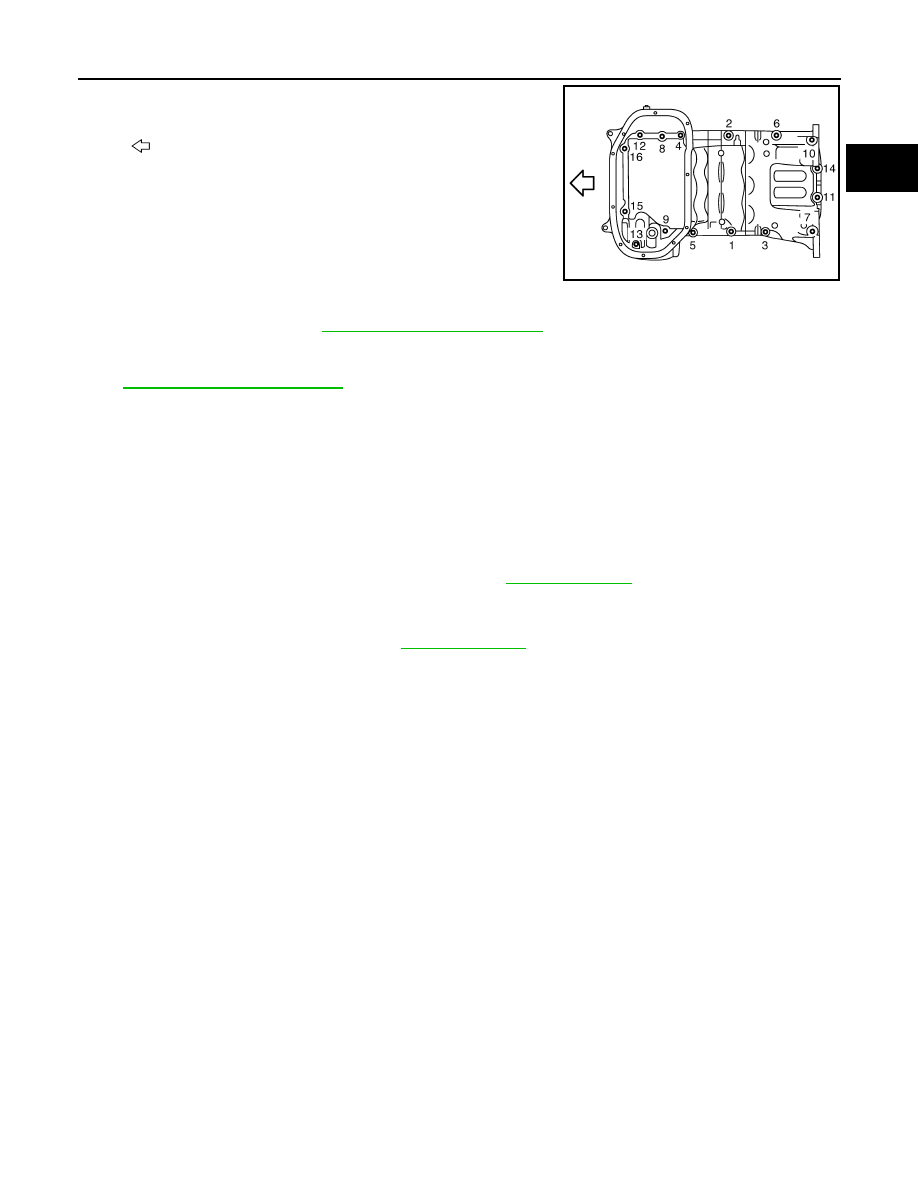
• Tighten mounting bolts in numerical order as shown in the fig-

ure.

• There are three types of mounting bolts. Refer to the following

for locating bolts.

3.

Install oil strainer to oil pump.

4.

Install oil pan (lower). Refer to 

EM-44, "Exploded View (AWD)"

.

5.

Install oil pan drain plug.
• Refer to the figure of components of former page for installation direction of drain plug washer. Refer to

EM-44, "Exploded View (AWD)"

.

6.

Install in the reverse order of removal after this step.
NOTE:
At least 30 minutes after oil pan is installed, pour engine oil.

AWD : Inspection

INFOID:0000000003139142

INSPECTION AFTER REMOVAL

Clean oil strainer if any object attached.

INSPECTION AFTER INSTALLATION

1.

Check the engine oil level and adjust engine oil. Refer to 

LU-6, "Inspection"

.

2.

Start engine, and check there is no leakage of engine oil.

3.

Stop engine and wait for 10 minutes.

4.

Check the engine oil level again. Refer to 

LU-6, "Inspection"

.

: Engine front

M8 

×

 25 mm (0.98 in)

: 3, 6, 8, 9, 11, 12, 14, 15, 16

M8 

×

 50 mm (1.97 in)

: 2

M8 

×

 90 mm (3.54 in)

: 1, 4, 5, 7, 10, 13

JPBIA0022ZZ

EM-104

< DISASSEMBLY AND ASSEMBLY >

CYLINDER HEAD

CYLINDER HEAD

Exploded View

INFOID:0000000003139143

Disassembly and Assembly

INFOID:0000000003139145

DISASSEMBLY

1.

Remove the following parts:
• Intake manifold collector: Refer to 

EM-29, "Exploded View"

.

• Rocker cover and spark plug: Refer to 

EM-47, "Exploded View"

.

• Fuel tube and fuel injector assembly: Refer to 

EM-37, "Exploded View"

.

• Intake manifold: Refer to 

EM-32, "Exploded View"

.

• Exhaust manifold: Refer to 

EM-34, "Exploded View"

.

• Water inlet and thermostat assembly: Refer to 

CO-21, "Exploded View"

.

• Water outlets (front and rear), water pipe and heater pipe: Refer to 

CO-23, "Exploded View"

.

• Timing chain: Refer to 

EM-50, "Exploded View"

.

1.

Valve lifter

2.

Valve collet

3.

Valve spring retainer

4.

Valve spring

5.

Valve oil seal

6.

Valve spring seat

7.

Valve guide

8.

Cylinder head bolt

9.

Spark plug

10. Spark plug tube

11.

Cylinder head (bank 1)

12. Valve seat (EXH)

13.  Valve (INT)

14. Valve (EXH)

15. Valve seat (EXH)

16. Cylinder head gasket (bank 1)

17. Cylinder head gasket (bank 2)

18. Cylinder head (bank 2)

19. Engine rear lower slinger

A.

Refer to 

EM-104

: Apply high strength thread locking sealant or equivalent.

Refer to 

GI-4, "Components"

 for symbols not described on the above.

JPBIA1826GB

CYLINDER HEAD

EM-105

< DISASSEMBLY AND ASSEMBLY >

C

D

E

F

G

H

I

J

K

L

M

A

EM

N

P

O

• Rear timing chain case: Refer to 

EM-92, "Exploded View"

.

• Camshaft: Refer to 

EM-67, "Exploded View"

.

2.

Remove cylinder head.
• Loosen cylinder head bolts in reverse order as shown in the

figure with cylinder head bolt wrench (commercial service tool)
and power tool.

3.

Remove cylinder head gaskets.

4.

Remove valve lifter.
• Identify installation positions, and store them without mixing them up.

5.

Remove valve collet.
• Compress valve spring with the valve spring compressor [SST:

KV10116200 (J-26336-A)] (A), the attachment [SST:
KV10115900 (J26336-20)] (C) and the adapter [SST:
KV10109220 (

)] (B). Remove valve collet with a magnet

hand.

CAUTION:

When working, take care not to damage valve lifter holes.

6.

Remove valve spring retainer, valve spring and valve spring seat.

7.

Push valve stem to combustion chamber side, and remove valve.
• Identify installation positions, and store them without mixing them up.

8.

Remove valve oil seal using the valve oil seal puller [SST:
KV10107902 (J38959)] (A).

9.

Remove valve seat, if valve seat must be replaced.

A

:  Bank  1

B

:  Bank  2

: Engine front

JPBIA0172ZZ

JPBIA0180ZZ

JPBIA0177ZZ

EM-106

< DISASSEMBLY AND ASSEMBLY >

CYLINDER HEAD

• Bore out old seat until it collapses. Boring should not continue beyond the bottom face of the seat

recess in cylinder head. Set the machine depth stop to ensure this. Refer to 

EM-142, "Cylinder Head"

.

CAUTION:

Prevent to scratch cylinder head by excessive boring.

10. Remove valve guide, if valve guide must be replaced.
a.

To remove valve guide, heat cylinder head to 110 to 130

°

C (230

to 266

°

F) by soaking in heated oil (A).

b.

Drive out valve guide with a press [under a 20 kN (2 ton, 2.2 US
ton, 2.0 lmp ton) pressure] or a hammer and the valve guide drift
(commercial service tool).

WARNING:

Cylinder head contains heat. When working, wear protec-
tive equipment to avoid getting burned.

11. Remove spark plug tube, as necessary.

• Using a pliers, pull spark plug tube out of cylinder head. 

CAUTION:

• Take care not to damage cylinder head.
• Once removed, spark plug tube will be deformed and cannot be reused. Never remove it unless

absolutely necessary.

ASSEMBLY

1.

If valve guide is removed in step 10 (DISASSEMBLY), install it. 
Replace with oversized [0.2 mm (0.008 in)] valve guide.

a.

Using the valve guide reamer (commercial service tool) (A),
ream cylinder head valve guide hole.

JPBIA0184ZZ

SEM931C

Valve guide hole diameter (for service parts):

Intake and exhaust

: Refer to 

EM-142, "Cylinder Head"

.

JPBIA0185ZZ


Content   ..  724  725  726  727   ..