Infiniti EX35. Manual - part 721


  Index      Infiniti     Infiniti EX35 - service repair manual 2008 year


Search            


Content   ..  719  720  721  722   ..


Infiniti EX35. Manual - part 721


ENGINE ASSEMBLY

EM-83

< REMOVAL AND INSTALLATION >

C

D

E

F

G

H

I

J

K

L

M

A

EM

N

P

O

Inspection for Leakage

The following are procedures for checking fluids leakage, lubricates leakage and exhaust gases leakage.

• Before starting engine, check oil/fluid levels including engine coolant and engine oil. If less than required

quantity, fill to the specified level. Refer to 

MA-10, "Fluids and Lubricants"

.

• Use procedure below to check for fuel leakage.
- Turn ignition switch “ON” (with engine stopped). With fuel pressure applied to fuel piping, check for fuel leak-

age at connection points.

- Start engine. With engine speed increased, check again for fuel leakage at connection points.
• Run engine to check for unusual noise and vibration.
• Warm up engine thoroughly to check there is no leakage of fuel, exhaust gases, or any oil/fluids including

engine oil and engine coolant.

• Bleed air from lines and hoses of applicable lines, such as in cooling system.
• After cooling down engine, again check oil/fluid levels including engine oil and engine coolant. Refill to the

specified level, if necessary.

Summary of the inspection items:

*: Transmission/transaxle/CVT fluid, power steering fluid, brake fluid, etc.
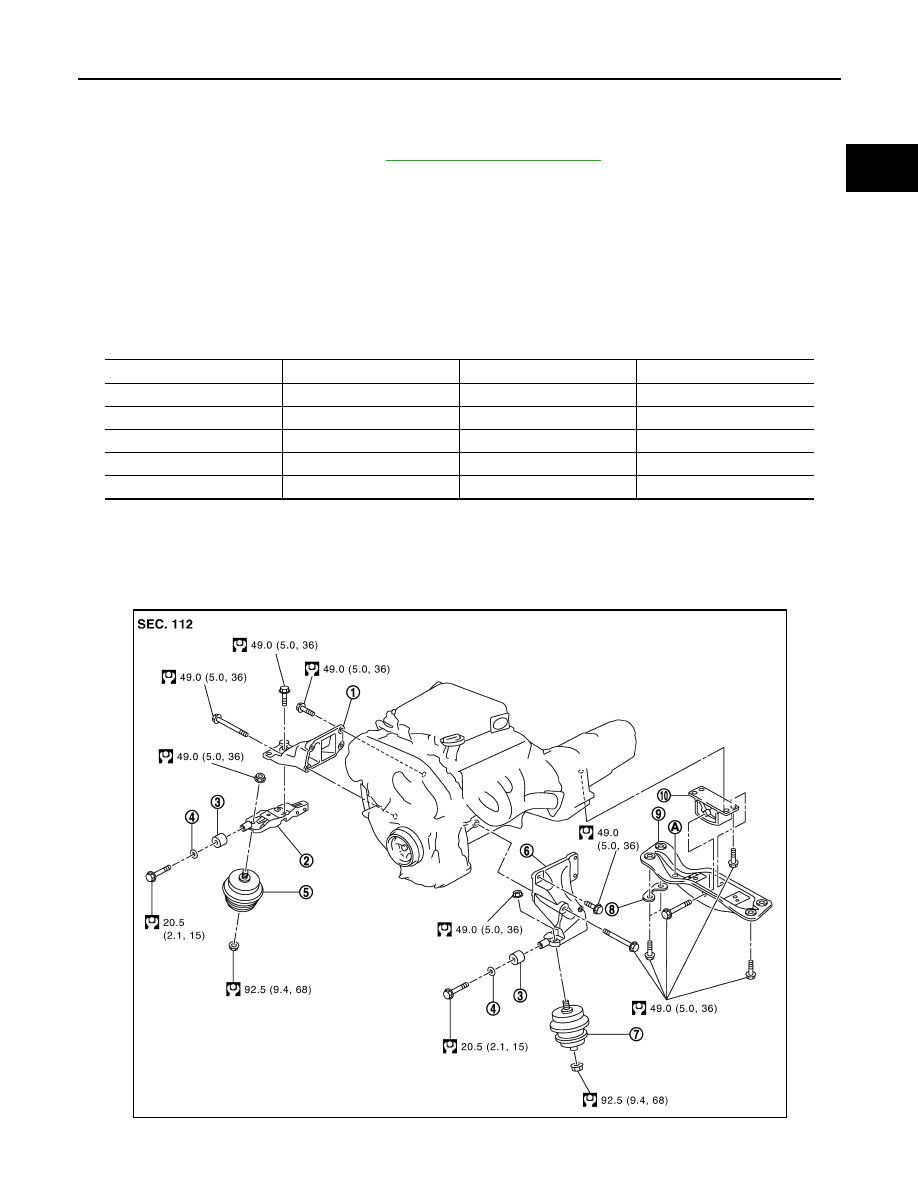
AWD

AWD : Exploded View

INFOID:0000000003139128

Items

Before starting engine

Engine running

After engine stopped

Engine coolant

Level

Leakage

Level

Engine oil

Level

Leakage

Level

Other oils and fluid*

Level

Leakage

Level

Fuel

Leakage

Leakage

Leakage

Exhaust gases

Leakage

JPBIA1291GB

EM-84

< REMOVAL AND INSTALLATION >

ENGINE ASSEMBLY

AWD : Removal and Installation

INFOID:0000000003139129

WARNING:

• Situate the vehicle on a flat and solid surface.
• Place chocks at front and back of rear wheels.
• For engines not equipped with engine slingers, attach proper slingers and bolts described in PARTS

CATALOG.

CAUTION:

• Always be careful to work safely, avoid forceful or uninstructed operations.
• Never start working until exhaust system and engine coolant are cool enough.
• If items or work required are not covered by the engine section, refer to the applicable sections.
• Always use the support point specified for lifting.
• Use either 2-pole lift type or separate type lift as best you can. If board-on type is used for unavoid-

able reasons, support at rear axle jacking point with transmission jack or similar tool before starting
work, in preparation for the backward shift of center of gravity.

• For supporting points for lifting and jacking point at rear axle, refer to 

GI-29, "Garage Jack and

Safety Stand and 2-Pole Lift"

.

REMOVAL

Outline

At first, remove the engine, the transmission assembly, the transfer assembly and the front final drive assem-
bly with front suspension member downward. Then separate the engine, the transmission assembly, the trans-
fer and the front final drive assembly.

Preparation

1.

Release fuel pressure. Refer to 

EC-538, "Inspection"

.

2.

Disconnect both battery terminals. Refer to 

PG-103, "Exploded View"

.

3.

Drain engine coolant from radiator. Refer to 

CO-7, "Draining"

.

CAUTION:

• Perform this step when engine is cold.
• Never spill engine coolant on drive belt.

4.

Remove the following parts:
• Radiator reservoir tank: Refer to 

CO-13, "Exploded View"

.

• Engine cover: Refer to 

EM-25, "Exploded View"

.

• Front road wheel and tires (power tool)
• Engine undercover (power tool)
• Front cross bar: Refer to 

FSU-37, "Exploded View"

.

• Cowl top cover: Refer to 

EXT-22, "Exploded View"

.

• Air duct and air cleaner case assembly (RH and LH): Refer to 

EM-27, "Exploded View"

.

• Cooling fan assembly: Refer to 

CO-16, "Exploded View"

.

5.

Discharge refrigerant from A/C circuit. Refer to 

HA-26, "Collection and Charge"

.

6.

Remove radiator hoses (upper and lower). Refer to 

CO-13, "Exploded View"

.

Engine Room LH

1.

Disconnect heater hose from vehicle-side, and fit a plug onto hose end to prevent engine coolant leakage.

2.

Disconnect A/C piping from A/C compressor, and temporarily fasten it on vehicle with a rope. Refer to 

HA-

39, "Exploded View"

.

3.

Disconnect brake booster vacuum hose.

4.

Disconnect ground cables.

1.

Engine mounting bracket (RH)

2.

Engine mounting bracket (RH) (low-
er)

3.

Dynamic damper

4.

Washer

5.

Engine mounting insulator (RH)

6.

Engine mounting bracket (LH)

7.

Engine mounting insulator (LH)

8.

Heat insulator

9.

Rear engine mounting member

10.

Engine mounting insulator (rear)

A.

Front mark

Refer to 

GI-4, "Components"

 for symbols in the figure.

ENGINE ASSEMBLY

EM-85

< REMOVAL AND INSTALLATION >

C

D

E

F

G

H

I

J

K

L

M

A

EM

N

P

O

Engine Room RH

1.

Disconnect battery positive cable vehicle side and temporarily fasten it on engine. 

2.

Disconnect all clips and connectors of the engine room harness from engine back side.

3.

Disconnect fuel feed hose (with damper) and EVAP hose. Refer to 

EM-37, "Exploded View"

.

CAUTION:

Fit plugs onto disconnected hoses to prevent fuel leakage.

4.

Remove reservoir tank of power steering oil pump and piping from vehicle, and temporarily secure them
on engine. Refer to 

ST-52, "AWD : Exploded View"

.

CAUTION:

When temporarily securing, keep the reservoir tank upright to avoid a fluid leakage.

Vehicle Inside

Follow procedure below to disconnect engine room harness connectors at passenger room side, and tempo-
rarily secure them on engine.

1.

Remove passenger-side kicking plate and dash side finisher. Refer to 

INT-20, "Exploded View"

.

2.

Disconnect engine room harness connectors at unit sides TCM, ECM and other.

3.

Disengage intermediate fixing point. Pull out engine room harnesses to engine room side, and temporarily
secure them on engine.

CAUTION:

• When pulling out harnesses, take care not to damage harnesses and connectors.
• After temporarily securing, cover connectors with vinyl or similar material to protect against for-

eign material adhesion.

Vehicle Underbody

1.

Remove A/T fluid cooler hoses and power steering oil pump oil cooler hoses.
• Install plug to avoid leakage of A/T fluid and power steering fluid.

2.

Disconnect heated oxygen sensor 2 harness. Refer to 

EX-6, "Removal and Installation"

.

3.

Remove three way catalyst and exhaust front tube. Refer to 

EX-5, "Exploded View"

.

4.

Disconnect steering lower joint at power steering gear assembly side, and release steering lower shaft.
Refer to 

ST-23, "Exploded View"

.

5.

Remove rear propeller shaft. Refer to 

DLN-89, "Exploded View"

.

6.

Remove front drive shaft (both side). Refer to 

FAX-23, "Exploded View"

.

7.

Disconnect harness connector from transmission assembly and transfer assembly.

8.

Disengage A/T control rod at control device assembly side. Then, temporarily secure it on the transmis-
sion assembly, so that it does not sag. Refer to 

TM-158, "AWD : Exploded View"

.

9.

Remove rear plate cover from oil pan (upper). Then remove bolts fixing drive plate to torque converter.
Refer to 

EM-100, "AWD : Exploded View"

.

10. Remove bolts fixing the transmission assembly to lower rear side of oil pan (upper). Refer to 

EM-100,

"AWD : Exploded View"

.

11. Remove front stabilizer connecting rod from transverse link. Refer to 

FSU-32, "Exploded View"

.

12. Remove lower ends of left and right steering knuckle from transverse link. Refer to 

ST-34, "AWD :

Exploded View"

.

13. Separate steering outer sockets from steering knuckle. Refer to 

ST-34, "AWD : Exploded View"

.

14. Remove transverse links mounting bolts at suspension member side. Refer to 

FSU-32, "Exploded View"

.

Removal Work

EM-86

< REMOVAL AND INSTALLATION >

ENGINE ASSEMBLY

1.

Use a manual lift table caddy (commercial service tool) or equiv-
alently rigid tool such as a transmission jack. Securely support
bottom of suspension member and transmission.

CAUTION:

Put a piece of wood or something similar as the supporting
surface, secure a completely stable condition.

2.

Remove rear engine mounting member bolts.

3.

Remove front suspension member mounting bolts and nuts. Refer to 

FSU-37, "Exploded View"

.

4.

Carefully lower jack, or raise lift to remove the engine, transmission assembly, transfer, front final drive
assembly and front suspension member. When performing work, observe the following caution:

CAUTION:

• Confirm there is no interference with the vehicle.
• Check that all connection points have been disconnected.
• Keep in mind the center of the vehicle gravity changes. If necessary, use jack(s) to support the

vehicle at rear jacking point(s) to prevent it from falling it off the lift.

Separation Work

1.

Install engine slingers into front of cylinder head (bank 1) and
rear of cylinder head (bank 2).

• To protect rocker cover against damage caused by tilting of

engine slinger, insert spacer between cylinder head and
engine rear lower slinger (3), in direction shown in the figure.

NOTE:
Spacer (2) is a component part of engine rear upper slinger
assembly.

2.

Remove power steering oil pump from engine side. Refer to 

ST-45, "Exploded View"

.

3.

Remove engine mounting insulators (RH and LH) under side nuts with power tool.

4.

Lift with hoist and separate the engine, the transmission assembly, the transfer assembly and the front
final drive assembly from front suspension member.

CAUTION:

• Before and during this lifting, always check if any harnesses are left connected.
• Never damage to and oil/grease smearing or spills onto engine mounting insulator.

5.

Remove alternator. Refer to 

CHG-27, "AWD : Exploded View"

.

PBIC0804E

1

: Engine front slinger

2

: Engine rear upper slinger

3

: Spacer

4

: Engine rear lower slinger

A

:  Bank  1

B

:  Bank  2

: Engine front

Slinger bolts:

: 28.0 N·m (2.9 kg-m, 21 ft-lb)

JPBIA0157ZZ

1

: Engine rear upper slinger

: Engine front

JPBIA0158ZZ


Content   ..  719  720  721  722   ..