Infiniti EX35. Manual - part 710


  Index      Infiniti     Infiniti EX35 - service repair manual 2008 year


Search            


Content   ..  708  709  710  711   ..


Infiniti EX35. Manual - part 710


FUEL INJECTOR AND FUEL TUBE

EM-39

< ON-VEHICLE REPAIR >

C

D

E

F

G

H

I

J

K

L

M

A

EM

N

P

O

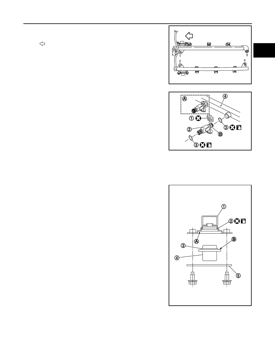
10. Loosen mounting bolts in reverse order as shown in the figure,

and remove fuel tube and fuel injector assembly.

CAUTION:

Never tilt fuel tube, or remaining fuel in pipes may flow out
from pipes.

11. Remove fuel injector (2) from fuel tube (4) as follows:

a.

Open and remove clip (1).

b.

Remove fuel injector from fuel tube by pulling straight.

CAUTION:

• Be careful with remaining fuel that may go out from fuel

tube.

• Be careful not to damage injector nozzles during removal.
• Never bump or drop fuel injector.
• Never disassemble fuel injector.

12. Remove fuel sub-tube and fuel damper, if necessary.

INSTALLATION

1.

Install fuel damper (4) as follows:

a.

Install new O-ring (2) to fuel tube (1) as shown. When handling
new O-ring, be careful of the following caution:

CAUTION:

• Handle O-ring with bare hands. Never wear gloves.
• Lubricate O-ring with new engine oil.
• Never clean O-ring with solvent.
• Check that O-ring and its mating part are free of foreign

material.

• When installing O-ring, be careful not to scratch it with

tool or fingernails. Also be careful not to twist or stretch
O-ring. If O-ring was stretched while it was being
attached, never insert it quickly into fuel tube.

• Insert new O-ring straight into fuel tube. Never twist it.

b.

Install spacer (3) to fuel damper.

c.

Insert fuel damper straight into fuel tube.

CAUTION:

• Insert straight, checking sure that the axis is lined up.
• Never pressure-fit with excessive force.

• Insert fuel damper until (B) is touching (A) of fuel tube.

d.

Tighten bolts evenly in turn.
• After tightening bolts, check that there is no gap between fuel damper cap (5) and fuel tube.

2.

Install fuel sub-tube.
• When handling new O-rings, be careful of the following caution:

CAUTION:

• Handle O-ring with bare hands. Never wear gloves.

: Engine front

JPBIA0034ZZ

3

: O-ring

A

: Installed condition

B

: Clip mounting groove

JPBIA0036ZZ

Reference value

: 130 N (13.3 kg, 29.2 lb)

JPBIA0316ZZ

EM-40

< ON-VEHICLE REPAIR >

FUEL INJECTOR AND FUEL TUBE

• Lubricate O-ring with new engine oil.
• Never clean O-ring with solvent.
• Check that O-ring and its mating part are free of foreign material.
• When installing O-ring, be careful not to scratch it with tool or fingernails. Also be careful not

to twist or stretch O-ring. If O-ring was stretched while it was being attached, never insert it
quickly into fuel tube.

• Insert new O-ring straight into fuel tube. Never decenter or twist it.

• Insert fuel sub-tube straight into fuel tube.
• Tighten mounting bolts evenly in turn.
• After tightening mounting bolts, check that there is no gap between flange and fuel tube.

3.

Install new O-rings to fuel injector, paying attention to the following.

CAUTION:

• Upper and lower O-ring are different. Be careful not to confuse them.

• Handle O-ring with bare hands. Never wear gloves.
• Lubricate O-ring with new engine oil.
• Never clean O-ring with solvent.
• Check that O-ring and its mating part are free of foreign material.
• When installing O-ring, be careful not to scratch it with tool or fingernails. Also be careful not to

twist or stretch O-ring. If O-ring was stretched while it was being attached, never insert it quickly
into fuel tube.

• Insert O-ring straight into fuel injector. Never decenter or twist it.

4.

Install fuel injector to fuel tube as follows:

a.

Insert clip (3) into clip mounting groove (D) on fuel injector (5).

CAUTION:

• Never reuse clip. Replace it with a new one.
• Be careful to keep clip from interfering with O-ring. If

interference occurs, replace O-ring.

b.

Insert fuel injector into fuel tube (1) with clip attached.
• Insert it while matching it to the axial center.
• Insert fuel injector so that protrusion (A) of fuel tube matches

cutout (B) of clip.

• Check that fuel tube flange (E) is securely fixed in flange fixing

groove (C) on clip.

c.

Check that installation is complete by checking that fuel injector
does not rotate or come off.
• Check that protrusions of fuel injectors are aligned with cut-

outs of clips after installation.

5.

Install fuel tube and fuel injector assembly to intake manifold.

CAUTION:

Be careful not to let tip of injector nozzle come in contact with other parts.

Fuel tube side

: Black

Nozzle side

: Green

2

: O-ring (Black)

4

: O-ring (Green)

JPBIA0037ZZ

FUEL INJECTOR AND FUEL TUBE

EM-41

< ON-VEHICLE REPAIR >

C

D

E

F

G

H

I

J

K

L

M

A

EM

N

P

O

• Tighten mounting bolts in two steps in numerical order as

shown in the figure.

6.

Connect injector sub-harness.

7.

Install fuel sub tube mounting bolt.

8.

Connect fuel feed hose (with damper).
• Handling procedure of O-ring is the same as that of fuel damper and fuel sub-tube.
• Insert fuel damper straight into fuel sub-tube.
• Tighten mounting bolts evenly in turn.
• After tightening mounting bolts, check that there is no gap between flange and fuel sub-tube.

9.

Connect quick connector between fuel feed hose (with damper) and centralized under-floor piping con-
nection as follows:

a.

Check no foreign substances are deposited in and around centralized under-floor piping and quick con-
nector, and no damage on them.

b.

Thinly apply new engine oil around centralized under-floor piping from tip end to spool end.

c.

Align center to insert quick connector straightly into centralized under-floor piping.
• Insert quick connector to centralized under-floor piping until top spool is completely inside quick connec-

tor and 2nd level spool exposes right below quick connector.

CAUTION:

• Carefully align center to avoid inclined insertion to prevent damage to O-ring inside quick con-

nector.

• Insert until you hear a “click” sound and actually feel the engagement.
• To avoid misidentification of engagement with a similar sound, be sure to perform the next step.

d.

Pull quick connector by hand holding position (A). Check it is
completely engaged (connected) so that it does not come out
from centralized under-floor piping (1).

e.

Install quick connector cap (3) to quick connector connection.

• Install quick connector cap with arrow (A) on surface facing in

direction of quick connector (fuel feed hose side).

CAUTION:

If quick connector cap cannot be installed smoothly, quick
connector may have not been installed correctly. Check the
connection again.

10. Install in the reverse order of removal after this step.

: Engine front

 1st step

: 10.1 N·m (1.0 kg-m, 7 ft-lb)

 2nd step

: 23.6 N·m (2.4 kg-m, 17 ft-lb)

JPBIA0034ZZ

PBIC3795E

1

: Centralized under-floor piping

2

: Fuel feed hose

B

: Under view

JPBIA0039ZZ

EM-42

< ON-VEHICLE REPAIR >

FUEL INJECTOR AND FUEL TUBE

Inspection

INFOID:0000000003139109

INSPECTION AFTER INSTALLATION

Check on Fuel Leakage

1.

Turn ignition switch “ON” (with the engine stopped). With fuel pressure applied to fuel piping, check there
are no fuel leakage at connection points.
NOTE:
Use mirrors for checking at points out of clear sight.

2.

Start the engine. With engine speed increased, check again that there are no fuel leakage at connection
points.

CAUTION:

Never touch the engine immediately after stopped, as the engine becomes extremely hot.


Content   ..  708  709  710  711   ..