Infiniti EX35. Manual - part 705
CAMSHAFT VALVE CLEARANCE
EM-19
< ON-VEHICLE MAINTENANCE >
C
D
E
F
G
H
I
J
K
L
M
A
EM
N
P
O
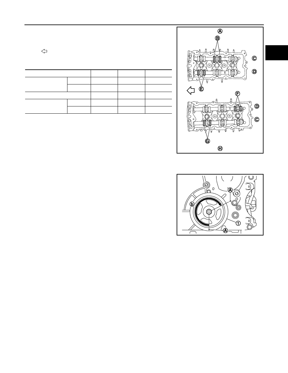
• By referring to the figure, measure the valve clearances at
locations marked “
×
” as shown in the table below (locations
indicated in the figure).
• No. 1 cylinder at compression TDC
c.
Rotate crankshaft 240 degrees clockwise (when viewed from engine front) to align No. 3 cylinder at TDC
its compression stroke.
NOTE:
Mark a position 240 degrees (b) from a corner of the hexagonal
part of crankshaft pulley mounting bolt as shown in the figure.
Use the hexagonal part as a guide.
: Engine front
Measuring position [bank 1 (A)]
No. 1 CYL.
No. 3 CYL.
No. 5 CYL.
No. 1 cylinder at com-
pression TDC
EXH (C)
×
(B)
INT (D)
×
(E)
Measuring position [bank 2 (H)]
No. 2 CYL.
No. 4 CYL.
No. 6 CYL.
No. 1 cylinder at com-
pression TDC
INT (D)
×
(F)
EXH (C)
×
(G)
JPBIA0165ZZ
1
: Crankshaft pulley
A
: Paint mark
JPBIA0166ZZ