Infiniti EX35. Manual - part 699
EC-538
< ON-VEHICLE MAINTENANCE >
[VQ35HR]
FUEL PRESSURE
ON-VEHICLE MAINTENANCE
FUEL PRESSURE
Inspection
INFOID:0000000003133683
FUEL PRESSURE RELEASE
With CONSULT-III
1.
Turn ignition switch ON.
2.
Perform “FUEL PRESSURE RELEASE” in “WORK SUPPORT” mode with CONSULT-III.
3.
Start engine.
4.
After engine stalls, crank it two or three times to release all fuel pressure.
5.
Turn ignition switch OFF.
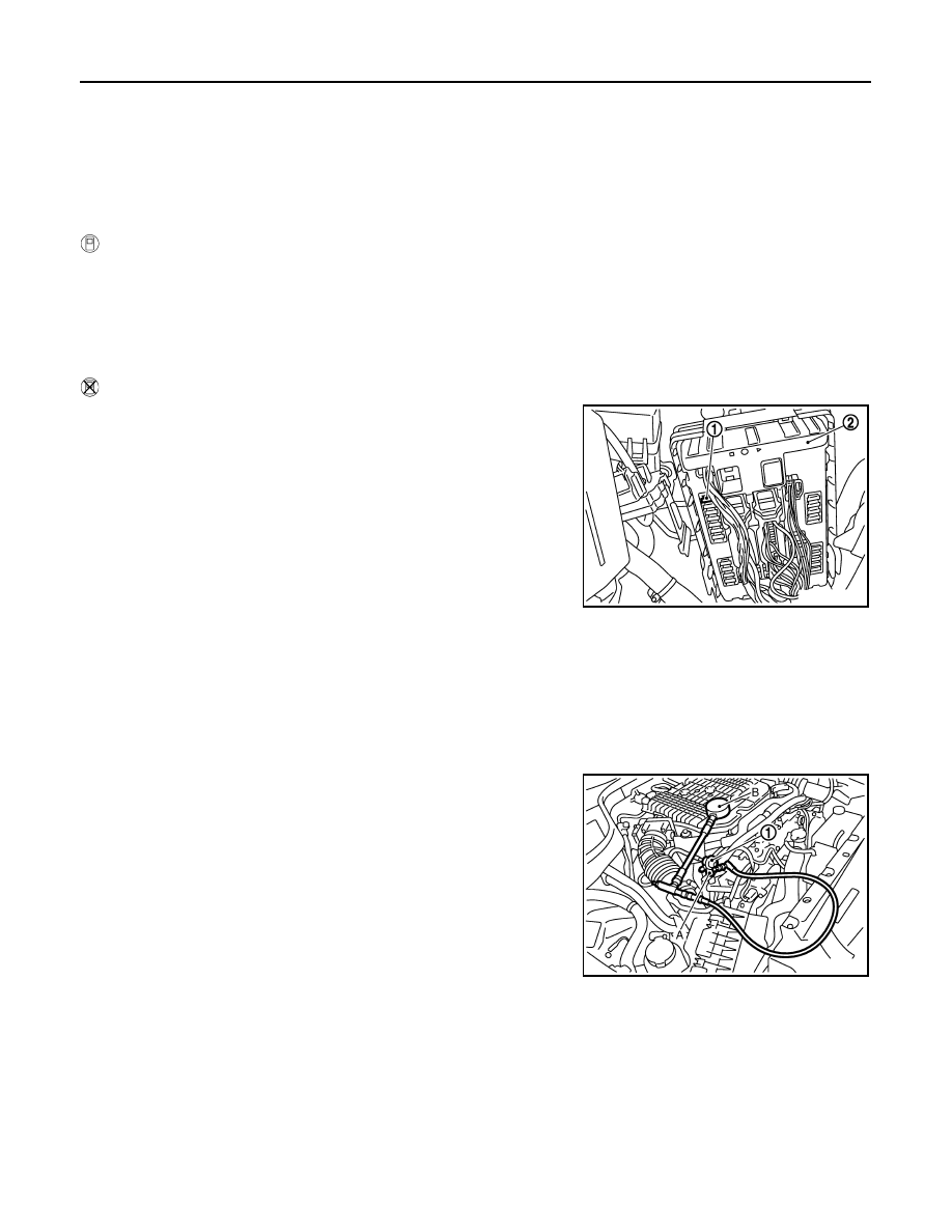
Without CONSULT-III
1.
Remove fuel pump fuse (1) located in IPDM E/R (2).
2.
Start engine.
3.
After engine stalls, crank it two or three times to release all fuel
pressure.
4.
Turn ignition switch OFF.
5.
Reinstall fuel pump fuse after servicing fuel system.
FUEL PRESSURE CHECK
CAUTION:
Before disconnecting fuel line, release fuel pressure from fuel line to eliminate danger.
NOTE:
• Prepare pans or saucers under the disconnected fuel line because the fuel may spill out. The fuel
pressure cannot be completely released because J50 models do not have fuel return system.
• Use Fuel Pressure Gauge Kit [SST:(J-44321)] to check fuel pressure.
1.
Release fuel pressure to zero.
2.
Install the inline fuel quick disconnected fitting (A) between fuel
damper (1) and injector tube.
3.
Connect the fuel pressure test gauge (quick connector adapter
hose) (B) to the inline fuel quick disconnected fitting.
4.
Turn ignition switch ON and check for fuel leakage.
5.
Start engine and check for fuel leakage.
6.
Read the indication of fuel pressure gauge.
7.
If result is unsatisfactory, check fuel hoses and fuel tubes for
clogging.
If OK, Replace “fuel filter and fuel pump assembly”.
If NG, Repair or replace malfunctioning part.
JMBIA0021ZZ
At idling
: Approximately 350 kPa (3.57 kg/cm
2
, 51 psi)
JMBIA0028ZZ