Infiniti EX35. Manual - part 663
EC-394
< COMPONENT DIAGNOSIS >
[VQ35HR]
P1564 ASCD STEERING SWITCH
3.
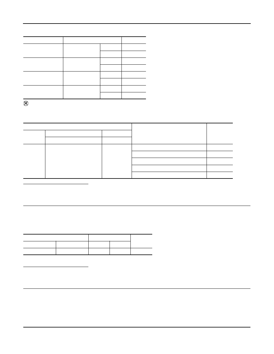
Check each item indication under the following conditions.
Without CONSULT-III
1.
Turn ignition switch ON.
2.
Check the voltage between ECM harness connector terminals under the following conditions.
Is the inspection result normal?
YES
>> GO TO 8.
NO
>> GO TO 3.
3.
CHECK ASCD STEERING SWITCH GROUND CIRCUIT FOR OPEN AND SHORT
1.
Turn ignition switch OFF.
2.
Disconnect ECM harness connector.
3.
Disconnect combination switch harness connector.
4.
Check the continuity between combination switch and ECM harness connector.
5.
Also check harness for short to ground and short to power.
Is the inspection result normal?
YES
>> GO TO 5.
NO
>> GO TO 4.
4.
DETECT MALFUNCTIONING PART
Check the following.
• Combination switch (spiral cable)
• Harness for open and short between ECM and combination switch
>> Repair open circuit or short to ground or short to power in harness or connectors.
5.
CHECK ASCD STEERING SWITCH INPUT SIGNAL CIRCUIT FOR OPEN AND SHORT
1.
Check the continuity between combination switch and ECM harness connector.
Monitor item
Condition
Indication
MAIN SW
MAIN switch
Pressed
ON
Released
OFF
CANCEL SW
CANCEL switch
Pressed
ON
Released
OFF
RESUME/ACC SW
RESUME/ACCEL-
ERATE switch
Pressed
ON
Released
OFF
SET SW
SET/COAST switch
Pressed
ON
Released
OFF
ECM
Condition
Voltage (V)
Connector
+
–
Terminal
Terminal
M107
101
(ASCD steering switch signal)
108
MAIN switch: Pressed
Approx. 0
CANCEL switch: Pressed
Approx. 1
SET/COAST switch: Pressed
Approx. 2
RESUME/ACCELERATE switch: Pressed
Approx. 3
All ASCD steering switches: Released
Approx. 4
Combination switch
ECM
Continuity
Connector
Terminal
Connector
Terminal
M303
16
M107
108
Existed