Infiniti EX35. Manual - part 654
EC-358
< COMPONENT DIAGNOSIS >
[VQ35HR]
P1226, P1235 TP SENSOR
P1226, P1235 TP SENSOR
Description
INFOID:0000000003133517
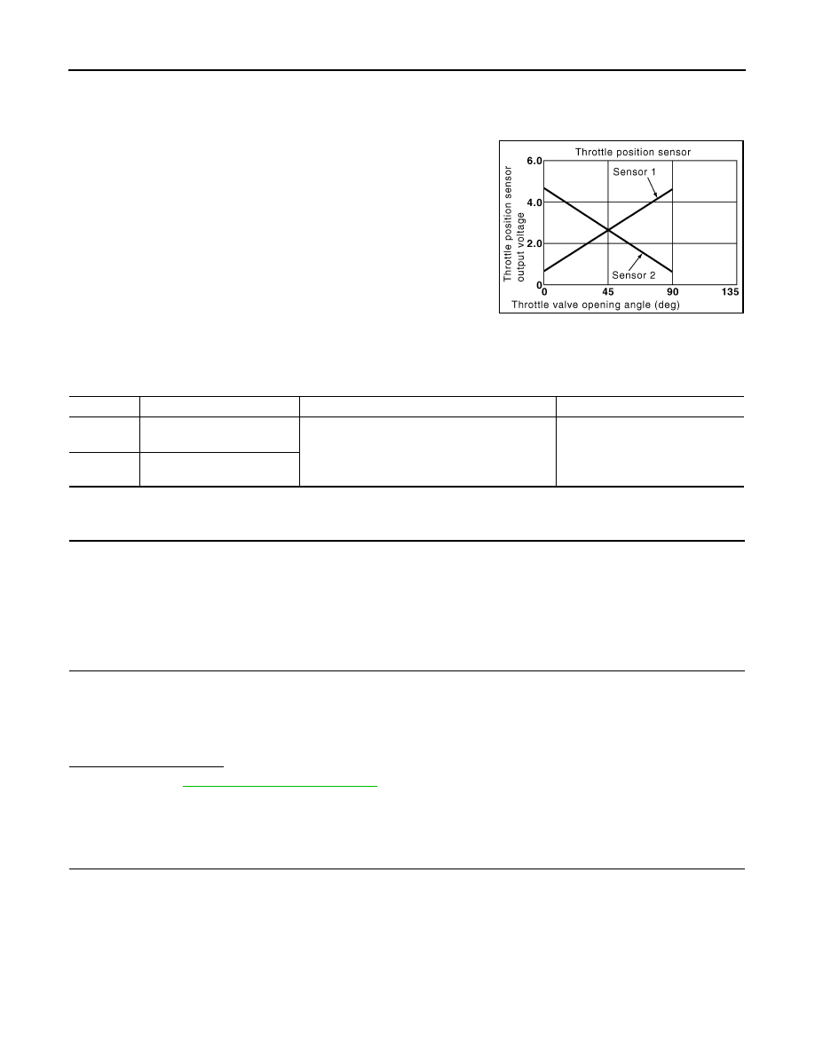
Electric throttle control actuator consists of throttle control motor,
throttle position sensor, etc. The throttle position sensor responds to
the throttle valve movement.
The throttle position sensor has two sensors. These sensors are a
kind of potentiometers which transform the throttle valve position into
output voltage, and emit the voltage signal to the ECM. In addition,
these sensors detect the opening and closing speed of the throttle
valve and feed the voltage signals to the ECM. The ECM judges the
current opening angle of the throttle valve from these signals and the
ECM controls the throttle control motor to make the throttle valve
opening angle properly in response to driving condition.
DTC Logic
INFOID:0000000003133518
DTC DETECTION LOGIC
DTC CONFIRMATION PROCEDURE
1.
PRECONDITIONING
If DTC Confirmation Procedure has been previously conducted, always turn ignition switch OFF and wait at
least 10 seconds before conducting the next test.
TESTING CONDITION:
Before performing the following procedure, confirm that battery voltage is more than 10 V at idle.
>> GO TO 2.
2.
PERFORM DTC CONFIRMATION PROCEDURE
1.
Turn ignition switch ON.
2.
Turn ignition switch OFF and wait at least 10 seconds.
3.
Turn ignition switch ON.
4.
Repeat steps 2 and 3 for 32 times.
5.
Check 1st trip DTC.
Is 1st trip DTC detected?
YES
>> Go to
NO
>> INSPECTION END
Diagnosis Procedure
INFOID:0000000003133519
1.
CHECK ELECTRIC THROTTLE CONTROL ACTUATOR VISUALLY
1.
Turn ignition switch OFF.
2.
Remove the intake air duct.
PBIB0145E
DTC No.
Trouble diagnosis name
DTC detecting condition
Possible cause
P1226
Closed throttle position learn-
ing performance (bank 1)
Closed throttle position learning is not performed
successfully, repeatedly.
• Electric throttle control actuator
(TP sensor 1 and 2)
P1235
Closed throttle position learn-
ing performance (bank 2)