Infiniti EX35. Manual - part 651
EC-346
< COMPONENT DIAGNOSIS >
[VQ35HR]
P1078, P1084 EVT CONTROL POSITION SENSOR
Is the inspection result normal?
YES
>> GO TO 5.
NO
>> Repair short to ground or short to power in harness or connectors.
5.
CHECK COMPONENTS
Check the following.
• Crankshaft position sensor (POS) (Refer to
EC-255, "Component Inspection"
• Camshaft position sensor (PHASE) (bank 2) (Refer to
EC-260, "Component Inspection"
• Battery current sensor (Refer to
EC-379, "Component Inspection"
.)
• EVAP control system pressure sensor (Refer to
EC-296, "Component Inspection"
.)
• Refrigerant pressure sensor (Refer to
Is the inspection result normal?
YES
>> GO TO 6.
NO
>> Replace malfunctioning component.
6.
CHECK APP SENSOR
EC-423, "Component Inspection"
Is the inspection result normal?
YES
>> GO TO 15.
NO
>> GO TO 7.
7.
REPLACE ACCELERATOR PEDAL ASSEMBLY
1.
Replace accelerator pedal assembly.
2.
Go to
EC-423, "Special Repair Requirement"
.
>> INSPECTION END
8.
CHECK EXHAUST VALVE TIMING CONTROL POSITION SENSOR GROUND CIRCUIT FOR OPEN AND
SHORT
1.
Turn ignition switch OFF.
2.
Disconnect ECM harness connector.
3.
Check the continuity between exhaust valve timing control position sensor harness connector and ECM
harness connector.
4.
Also check harness for short to ground and short to power.
Is the inspection result normal?
YES
>> GO TO 9.
NO
>> Repair open circuit or short to ground or short to power in harness or connectors.
9.
CHECK EXHAUST VALVE TIMING CONTROL POSITION SENSOR INPUT SIGNAL CIRCUIT FOR OPEN
AND SHORT
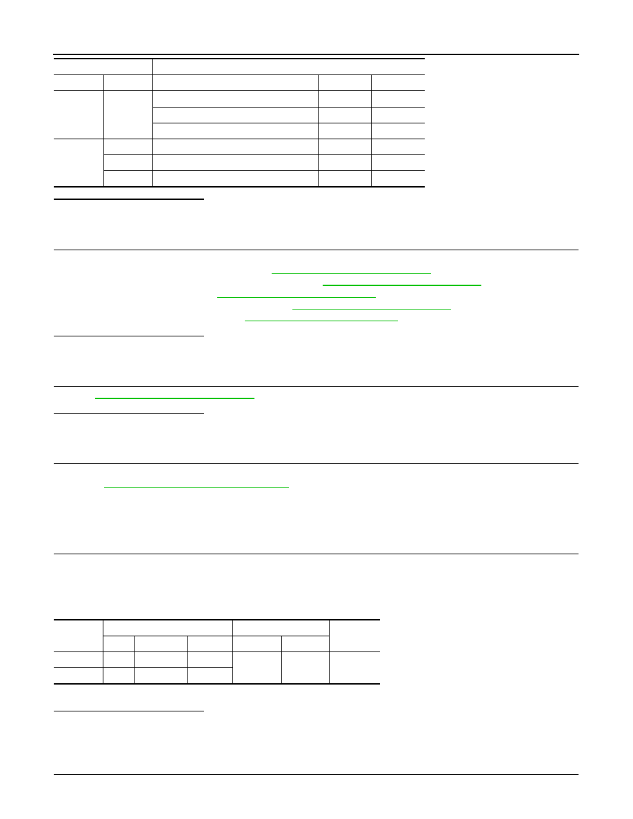
F102
64
CMP sensor (PHASE) (bank 2)
F18
1
EVT control position sensor (bank 2)
F19
1
Battery current sensor
E21
1
M107
103
APP sensor
E112
6
107
EVAP control system pressure sensor
B252
3
111
Refrigerant pressure sensor
E77
3
ECM
Sensor
Connector
Terminal
Name
Connector
Terminal
DTC
EVT control position sensor
ECM
Continuity
Bank
Connector
Terminal
Connector
Terminal
P1078
1
F4
2
F102
88
Existed
P1084
2
F19
2