Infiniti EX35. Manual - part 581
EC-66
< FUNCTION DIAGNOSIS >
[VQ35HR]
COOLING FAN CONTROL
COOLING FAN CONTROL
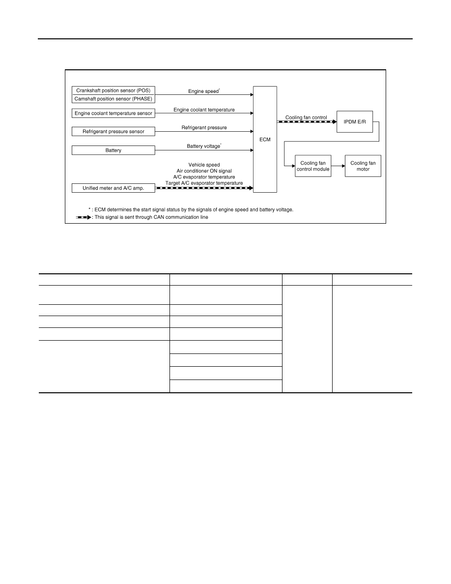
System Diagram
INFOID:0000000003133268
System Description
INFOID:0000000003133269
INPUT/OUTPUT SIGNAL CHART
*1: The ECM determines the start signal status by the signals of engine speed and battery voltage.
*2: This signal is sent to ECM through CAN communication line.
SYSTEM DESCRIPTION
ECM controls cooling fan speed corresponding to vehicle speed, engine coolant temperature, air conditioner
ON signal, refrigerant pressure, target A/C evaporator temperature and A/C evaporator temperature.
Cooling fan control signal is sent to IPDM E/R from ECM by CAN communication line. Then, IPDM E/R sends
ON/OFF pulse duty signal to cooling fan control module. Corresponding to this ON/OFF pulse duty signal,
cooling fan control module gives cooling fan motor operating voltage to cooling fan motors. Cooling fan speed
is controlled by duty cycle of cooling fan motor operating voltage sent from cooling fan control module.
JMBIA0075GB
Sensor
Input signal to ECM
ECM function
Actuator
Crankshaft position sensor (POS)
Camshaft position sensor (PHASE)
Engine speed*
1
Cooling fan
control
IPDM E/R
↓
Cooling fan control module
↓
Cooling fan motor
Engine coolant temperature sensor
Engine coolant temperature
Refrigerant pressure sensor
Refrigerant pressure
Battery
Battery voltage*
1
Unified meter and A/C amp.
Vehicle speed*
2
Air conditioner ON signal*
2
A/C evaporator temperature*
2
Target A/C evaporator temperature*
2