Infiniti EX35. Manual - part 558


  Index      Infiniti     Infiniti EX35 - service repair manual 2008 year


Search            


Content   ..  556  557  558  559   ..


Infiniti EX35. Manual - part 558


DLN-182

< DISASSEMBLY AND ASSEMBLY >

[REAR FINAL DRIVE: R200]

DIFFERENTIAL ASSEMBLY

10. Install drive gear on the mounting bolts.

CAUTION:

• Tighten bolts in a crisscross fashion.
• After tightening the bolts to the specified torque, tighten

the bolts additionally by turning the bolts 31 to 36
degrees.

11. Press side bearing inner races to differential case, using the drift

(A) [SST: KV38100300 (J-25523)] and the base (B) [SST:
ST33061000 (J-8107-2)].

CAUTION:

Never reuse side bearing inner race.

12. Install differential case assembly with side bearing outer races

into gear carrier.

13. Measure side bearing preload. If necessary, select the appropri-

ate side bearing adjusting washers. Refer to 

DLN-183, "AWD :

Adjustment"

.

14. Insert selected left and right side bearing adjusting washers in

place between side bearings and gear carrier. Refer to 

DLN-

183, "AWD : Adjustment"

.

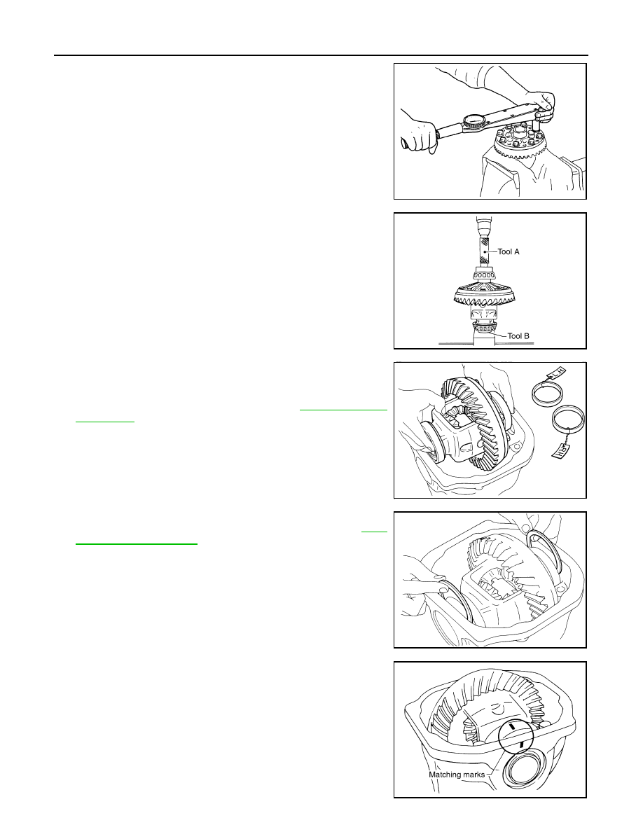
15. Align matching marks on bearing cap with that on gear carrier.
16. Install bearing caps and tighten bearing cap mounting bolts.

SDIA0247J

SPD353

SPD527

SPD558

SDIA1795E

DIFFERENTIAL ASSEMBLY

DLN-183

< DISASSEMBLY AND ASSEMBLY >

[REAR FINAL DRIVE: R200]

C

E

F

G

H

I

J

K

L

M

A

B

DLN

N

O

P

17. Using the drift (A) [SST: KV38100200 (J-26233)], drive side oil

seals until it becomes flush with the case end.

CAUTION:

• Never reuse oil seal.
• When installing, never incline oil seal.
• Apply multi-purpose grease onto oil seal lips, and gear oil

onto the circumference of oil seal.

18. Check and adjust drive gear runout, tooth contact, drive gear to

drive pinion backlash, and total preload torque. Refer to 

DLN-

183, "AWD : Adjustment"

.

Recheck above items. Readjust the above description, if neces-
sary.

19. Apply sealant (A) to mating surface of rear cover.

• Use Genuine Silicone RTV or equivalent. Refer to 

GI-15,

"Recommended Chemical Products and Sealants"

.

CAUTION:

Remove old sealant adhering to mounting surfaces. Also
remove any moisture, oil, or foreign material adhering to
application and mounting surfaces.

20. Install rear cover on gear carrier and tighten mounting bolts.

21. Install side flange with the following procedure.
a.

Attach the protector [SST: KV38107900 (J-39352)] to side oil
seal.

b.

After the side flange is inserted and the serrated part of side
gear has engaged the serrated part of flange, remove the pro-
tector.

c.

Put a suitable drift on the center of side flange, then drive it until sound changes.
NOTE:
When installation is completed, driving sound of the side flange turns into a sound that seems to affect the
whole final drive.

d.

Confirm that the dimension of the side flange installation mea-
surement (A) in the figure comes into the following.

AWD : Adjustment

INFOID:0000000003135839

TOTAL PRELOAD TORQUE

Before inspection and adjustment, drain gear oil.

1.

Secure final drive assembly onto an attachment [SST: KV38100800 (J-25604-01)].

2.

Remove side flanges.

SPD560

PDIA0961E

SDIA0822E

Standard

A

: 326 – 328 mm (12.83 – 12.91 in)

SDIA1039E

DLN-184

< DISASSEMBLY AND ASSEMBLY >

[REAR FINAL DRIVE: R200]

DIFFERENTIAL ASSEMBLY

3.

Rotate drive pinion back and forth 2 to 3 times to check for unusual noise and rotation malfunction.

4.

Rotate drive pinion at least 20 times to check for smooth opera-
tion of the bearing.

5.

Measure total preload with the preload gauge (A) [SST:
ST3127S000 (J-25765-A)].

NOTE:
Total preload torque = Pinion bearing preload torque + Side
bearing preload torque
• If measured value is out of the specification, disassemble it to check and adjust each part. Adjust the

pinion bearing preload and side bearing preload.
Adjust the pinion bearing preload first, then adjust the side bearing preload.

SIDE BEARING PRELOAD

Before inspection and adjustment, drain gear oil.
1.

Remove rear cover. Refer to 

DLN-176, "AWD : Disassembly"

.

2.

Make sure all parts are clean. Also, make sure the bearings are
well lubricated with gear oil.

3.

Place the differential case, with side bearings and bearing races
installed, into gear carrier.

4.

Insert left and right original side bearing adjusting washers in
place between side bearings and gear carrier.

Standard

Total preload torque

: Refer to 

DLN-207, "Pre-

load Torque"

.

PDIA0766J

When the preload torque is large

On pinion bearings:

Replace the collapsible spacer.

On side bearings:

Use thinner side bearing adjusting washers by the same amount to 
each side.

When the preload is small

On pinion bearings:

Tighten the drive pinion lock nut.

On side bearings:

Use thicker side bearing adjusting washers by the same amount to 
each side.

SPD527

SPD558

DIFFERENTIAL ASSEMBLY

DLN-185

< DISASSEMBLY AND ASSEMBLY >

[REAR FINAL DRIVE: R200]

C

E

F

G

H

I

J

K

L

M

A

B

DLN

N

O

P

5.

Install bearing caps in their correct locations and tighten bearing
cap mounting bolts.

6.

Turn the carrier several times to seat the bearings.

7.

Measure the turning torque of the carrier at the drive gear
mounting bolts with a spring gauge [SST: 

 (J-8129)].

8.

If the turning torque is outside the specification, use a thicker/
thinner side bearing adjusting washer to adjust.

CAUTION:

Select a side bearing adjusting washer for right and left
individually.

9.

Record the total amount of washer thickness required for the correct carrier side bearing preload.

DRIVE GEAR RUNOUT

1.

Remove rear cover. Refer to 

DLN-176, "AWD : Disassembly"

.

2.

Fit a dial indicator to the drive gear back face.

3.

Rotate the drive gear to measure runout.

• If the runout is outside of the repair limit, check drive gear

assembly condition; foreign material may be caught between
drive gear and differential case, or differential case or drive
gear may be deformed, etc.

CAUTION:

Replace drive gear and drive pinion gear as a set.

TOOTH CONTACT

Before inspection and adjustment, drain gear oil.
1.

Remove rear cover. Refer to 

DLN-176, "AWD : Disassembly"

.

SDIA1795E

Standard

Specification

: 34.2 – 39.2 N (3.5 – 4.0 kg, 
7.7 – 8.8 lb) of pulling force 
at the drive gear bolt

SPD194A

If the turning torque is less 
than the specified range:

Use a thicker thrust wash-
er.

If the turning torque is 
greater than the specifica-
tion:

Use a thinner thrust wash-
er.

SPD772

Limit

Drive gear runout

: Refer to 

DLN-207, "Drive 

Gear Runout"

.

SPD886


Content   ..  556  557  558  559   ..