Infiniti EX35. Manual - part 544


  Index      Infiniti     Infiniti EX35 - service repair manual 2008 year


Search            


Content   ..  542  543  544  545   ..


Infiniti EX35. Manual - part 544


DLN-126

< DISASSEMBLY AND ASSEMBLY >

[FRONT FINAL DRIVE: F160A]

DRIVE PINION

Disassembly

INFOID:0000000003135801

1.

Remove differential case assembly. Refer to 

DLN-112, "Disassembly"

.

2.

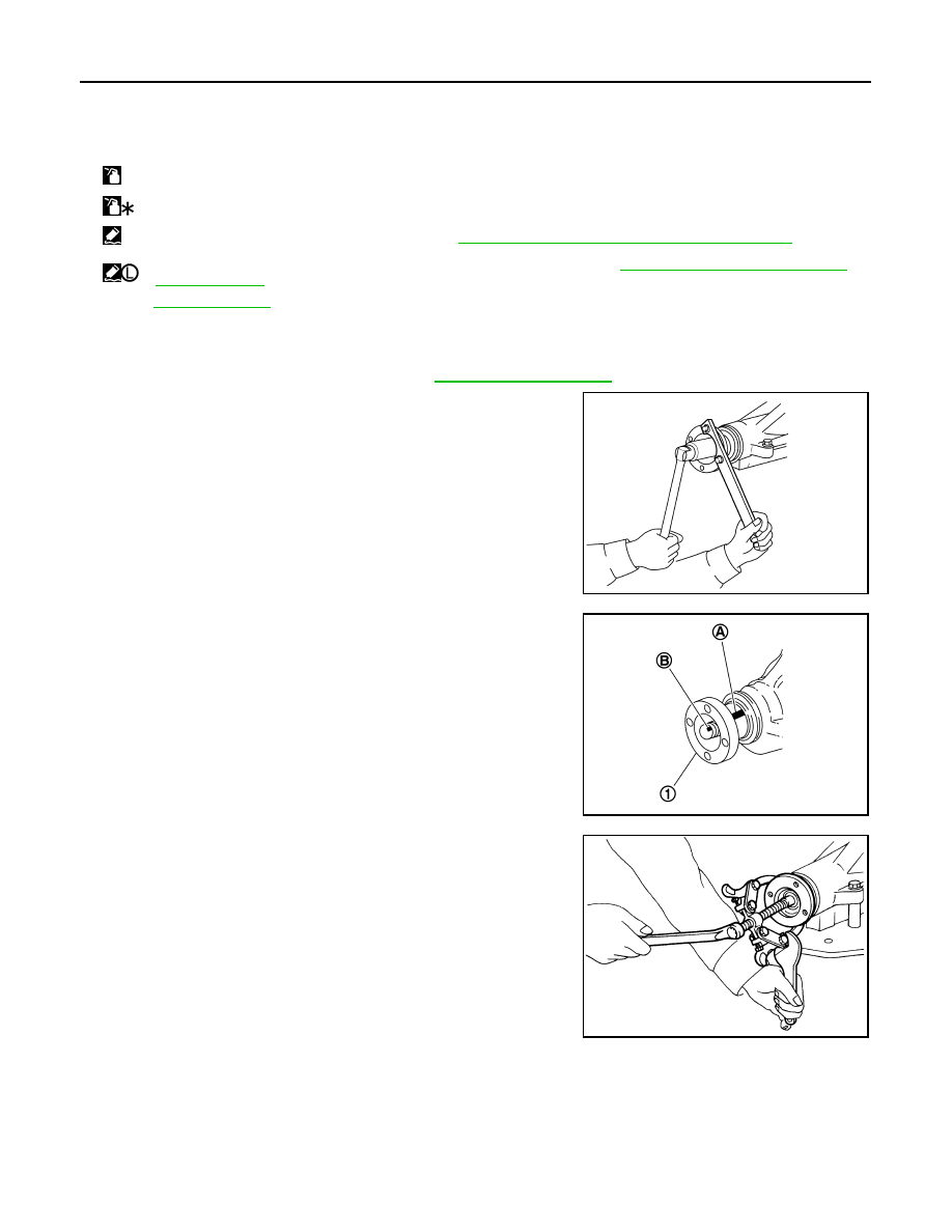
Remove drive pinion lock nut with a flange wrench.

3.

Put matching mark (B) on the end of drive pinion. The matching
mark should be in line with the matching mark (A) on companion
flange (1).

CAUTION:

For matching mark, use paint. Never damage companion
flange and drive pinion.
NOTE:
The matching mark (A) on the final drive companion flange (1)
indicates the maximum vertical runout position.
When replacing companion flange, matching mark is not neces-
sary.

4.

Remove companion flange using the suitable puller.

34. Side shaft bearing

35. Extension tube retainer 

36. Side shaft oil seal

37. Dust seal

38. Side shaft

A: 

Oil seal lip

B:

Screw hole

:

Apply gear oil.

:

Apply anti-corrosion oil.

:

Apply Genuine Silicone RTV or equivalent. Refer to 

GI-15, "Recommended Chemical Products and Sealants"

.

:

Apply Genuine Medium Strength Thread Locking Sealant or equivalent. Refer to 

GI-15, "Recommended Chemical Prod-

ucts and Sealants"

.

Refer to 

GI-4, "Components"

 for symbols not described above.

PDIA0798J

PDIA0799J

SDIA1132E

DRIVE PINION

DLN-127

< DISASSEMBLY AND ASSEMBLY >

[FRONT FINAL DRIVE: F160A]

C

E

F

G

H

I

J

K

L

M

A

B

DLN

N

O

P

5.

Press drive pinion assembly out of gear carrier.

CAUTION:

Never drop drive pinion assembly.

6.

Remove front oil seal.

7.

Remove pinion front bearing inner race.

8.

Remove drive pinion bearing adjusting washer and drive pinion
adjusting washer.

9.

Remove pinion rear bearing inner race and pinion height adjust-
ing washer with replacer (A) (commercial service tool).

10. Tap pinion front/rear bearing outer races uniformly a brass rod or

equivalent to removed.

CAUTION:

Never damage gear carrier.

Assembly

INFOID:0000000003135802

1.

Install pinion front and rear bearing outer races using drift (A)
[SST: ST37820000 (

)].

CAUTION:

• At first, using a hammer, tap bearing outer race until it

becomes flat to gear carrier.

• Never reuse pinion front and rear bearing outer race.

PDIA0800J

PDIA0801J

PDIA0677E

PDIA0803J

DLN-128

< DISASSEMBLY AND ASSEMBLY >

[FRONT FINAL DRIVE: F160A]

DRIVE PINION

2.

Temporarily install pinion height adjusting washer (1).

When hypoid gear set has been replaced

• Select pinion height adjusting washer. Refer to 

DLN-129,

"Adjustment"

.

When hypoid gear set has been reused

• Temporarily install the removed pinion height adjusting washer

or same thickness washer to drive pinion.

3.

Install selected pinion height adjusting washer (2) to drive pin-
ion. Press pinion rear bearing inner race (1) to it, using drift (A)
[SST: ST30032000 (J-26010-01)].

CAUTION:

• Pay attention to the direction of pinion height adjusting

washer. (Assemble as shown in the figure.)

• Never reuse pinion rear bearing inner race.

4.

Temporarily assemble removed drive pinion adjusting washer
and drive pinion bearing adjusting washer or same thickness of
them to drive pinion.

5.

Apply gear oil to pinion rear bearing, and assemble drive pinion
into gear carrier.

6.

Apply gear oil to pinion front bearing, and assemble pinion front
bearing inner race to drive pinion assembly.

CAUTION:

Never reuse pinion front bearing inner race.

7.

Using suitable spacer (A), press the pinion front bearing inner
race to drive pinion as far as drive pinion nut can be tightened.

8.

Adjust pinion bearing preload. If necessary, select the appropri-
ate drive pinion adjusting washer and drive pinion bearing
adjusting washer. Refer to 

DLN-129, "Adjustment"

.

9.

Using the drifts, install front oil seal as shown in figure.

CAUTION:

• Never reuse oil seal.
• When installing, never incline oil seal.
• Apply multi-purpose grease onto oil seal lips, and gear oil

onto the circumference of oil seal.

PDIA0971E

PDIA0805J

PDIA0681E

PDIA0807J

A: Drift [SST: ST33400001 (J-26082)]

B: Drift [SST: KV38102510 (

)]

PDIA0808J

DRIVE PINION

DLN-129

< DISASSEMBLY AND ASSEMBLY >

[FRONT FINAL DRIVE: F160A]

C

E

F

G

H

I

J

K

L

M

A

B

DLN

N

O

P

10. Install companion flange (1).

NOTE:
When reusing drive pinion, align the matching mark (B) of drive
pinion with the matching mark (A) of companion flange, and then
install companion flange (1).

11. Apply anti-corrosion oil to the thread and seat of new drive pin-

ion lock nut, and temporarily tighten drive pinion lock nut to drive
pinion.

CAUTION:

Never reuse drive pinion lock nut.

12. Tighten to drive pinion lock nut, while adjusting pinion bearing

preload torque.

CAUTION:

• Adjust to the lower limit of the drive pinion lock nut tight-

ening torque first.

• After adjustment, rotate drive pinion back and forth 2 to 3

times to check for unusual noise, rotation malfunction,
and other malfunctions.

13. Install differential case assembly. Refer to 

DLN-115, "Assembly"

.

CAUTION:

Never install carrier cover yet.

14. Check and adjust drive gear runout, tooth contact, drive gear to drive pinion backlash, and companion

flange runout. Refer to 

DLN-119, "Adjustment"

 and 

DLN-129, "Adjustment"

.

Recheck above items. Readjust the above description, if necessary.

15. Check total preload torque. Refer to 

DLN-119, "Adjustment"

.

16. Install carrier cover. Refer to 

DLN-115, "Assembly"

.

Adjustment

INFOID:0000000003135803

PINION GEAR HEIGHT

If the hypoid gear set has been replaced, select the pinion height adjusting washer.
1.

Use the formula below to calculate pinion height adjusting
washer thickness.

PDIA0799J

A: Preload gauge [SST: ST3127S000 (J-25765-A)]

Standard

Pinion bearing preload

: Refer to 

DLN-133, "Pre-

load Torque"

.

PDIA0802J

Washer selection equation:

T = T

0

 + (t

1

 t

2

)

T:

Correct washer thickness

T

0

:

Removed washer thickness

t

1

:

Old drive pinion head letter “H 

×

 0.01”

(“H”: machined tolerance 1/100 mm 

×

 100)

t

2

:

New drive pinion head letter “H 

×

 0.01”

(“H”: machined tolerance 1/100 mm 

×

 100)

SDIA0249J


Content   ..  542  543  544  545   ..