Infiniti EX35. Manual - part 537
DLN-98
< PREPARATION >
[FRONT FINAL DRIVE: F160A]
PREPARATION
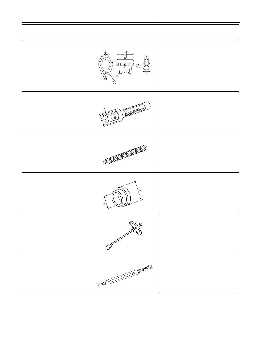
ST3306S001
(J-22888-D)
Differential side bearing puller set
1: ST33051001
(J-22888-20)
Puller
2: ST33061000
(J-8107-2)
Base
a: 28.5 mm (1.122 in) dia.
b: 38 mm (1.50 in) dia.
Removing and installing side bearing inner
race
ST33230000
(J-25805-01)
Drift
a: 51 mm (2.01 in) dia.
b: 41 mm (1.61 in) dia.
c: 28.5 mm (1.122 in) dia.
Installing side bearing inner race
ST30611000
(J-25742-1)
Drift bar
Installing side bearing outer race (Use with
KV31103000)
KV31103000
(J-38982)
Drift
a: 49 mm (1.93 in) dia.
b: 70 mm (2.76 in) dia.
Installing side bearing outer race
ST3127S000
(J-25765-A)
Preload gauge
Measuring pinion bearing preload and total
preload
(J-8129)
Spring gauge
Measuring turning torque
Tool number
(Kent-Moore No.)
Tool name
Description
NT072
ZZA1046D
S-NT090
ZZA1113D
ZZA0806D
NT127