Infiniti EX35. Manual - part 504


  Index      Infiniti     Infiniti EX35 - service repair manual 2008 year


Search            


Content   ..  502  503  504  505   ..


Infiniti EX35. Manual - part 504


DLK-230

< ON-VEHICLE REPAIR >

[INTELLIGENT KEY SYSTEM]

REAR DOOR

DOOR STRIKER : Removal and Installation

INFOID:0000000003556348

REMOVAL

Remove TORX bolts, and then remove door striker.

INSTALLATION

Install in the reverse order of removal.

CAUTION:

• Check rear door open/close, lock/unlock operation after installation.
• After installation, be sure to perform the fitting adjustment. Refer to 

DLK-229, "DOOR ASSEMBLY :

Adjustment"

.

DOOR HINGE

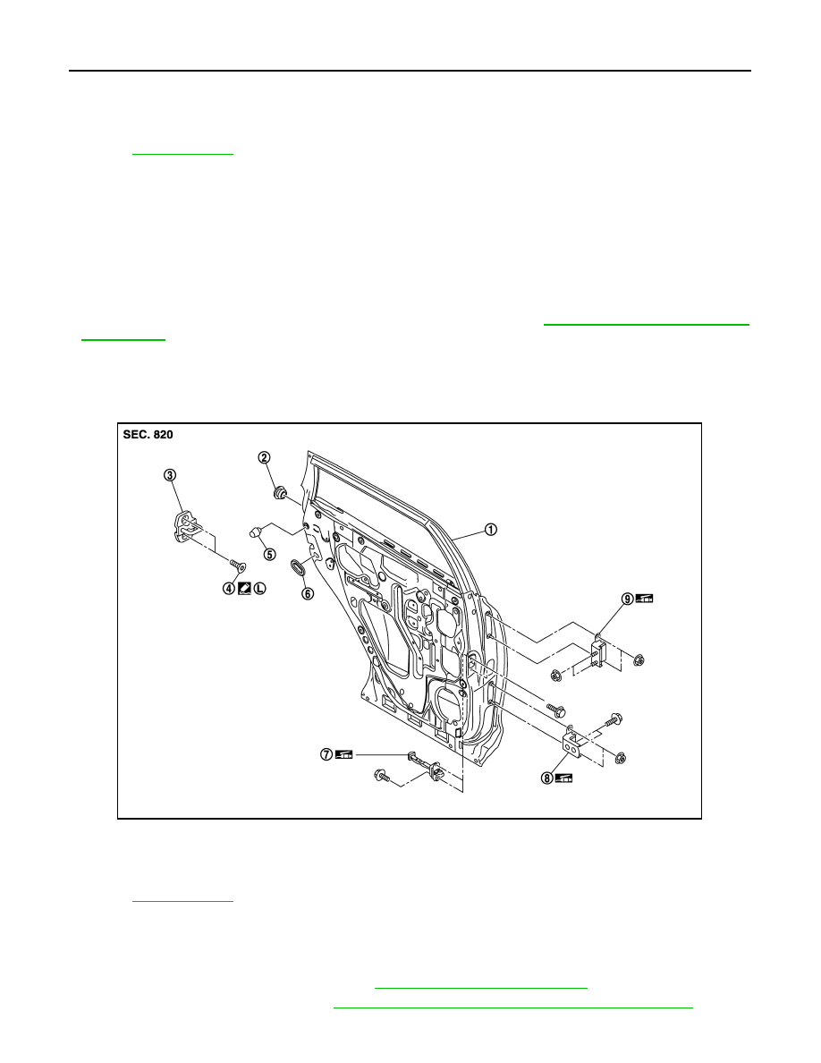
DOOR HINGE : Exploded View

INFOID:0000000003586773

DOOR HINGE : Removal and Installation

INFOID:0000000003556350

REMOVAL

1.

Remove center pillar lower garnish. Refer to 

INT-20, "Removal and Installation"

.

2.

Remove rear door assembly. Refer to 

DLK-228, "DOOR ASSEMBLY : Removal and Installation"

.

1.

Rear door panel

2.

Grommet

3.

Door striker

4.

TORX bolt

5.

Bumper rubber

6.

Seal rubber

7.

Door check link

8.

Door hinge (lower)

9.

Door hinge (upper)

Refer to 

GI-4, "Components"

 for symbols in the figure.

1.

Rear door panel

2.

Grommet

3.

Door striker

4.

TORX bolt

5.

Bumper rubber

6.

Seal rubber

7.

Door check link

8.

Door hinge (lower)

9.

Door hinge (upper)

Refer to 

GI-4, "Components"

 for symbols in the figure.

JMKIA1800ZZ

REAR DOOR

DLK-231

< ON-VEHICLE REPAIR >

[INTELLIGENT KEY SYSTEM]

C

D

E

F

G

H

I

J

L

M

A

B

DLK

N

O

P

3.

Remove rear door hinge mounting bolts and nuts (body side), and then remove door hinge.

INSTALLATION

Install in the reverse order of removal.

CAUTION:

• Check rear door open/close operation after installation.
• Check door hinge rotating part for poor lubrication. If necessary, apply body grease.
• When removing and installing rear door assembly, perform the fitting adjustment. Refer to 

DLK-229,

"DOOR ASSEMBLY : Adjustment"

.

• After installing, apply the touch-up paint (the body color) onto the head of door hinge mounting nuts.

DOOR CHECK LINK

DOOR CHECK LINK : Exploded View

INFOID:0000000003586774

DOOR CHECK LINK : Removal and Installation

INFOID:0000000003556352

REMOVAL

1.

Remove rear door finisher. Refer to 

INT-17, "Removal and Installation"

.

2.

Fully close the rear door window.

3.

Remove rear door speaker. Refer to 

AV-159, "Removal and Installation"

 (base audio without navigation),

or 

AV-415, "Removal and Installation"

 (BOSE audio without navigation), or 

AV-906, "Removal and Installa-

tion"

 (BOSE audio with navigation).

4.

Remove mounting bolts of the check link on the vehicle.

5.

Remove mounting bolts of the check link on door panel.

6.

Take door check link out from the hole of door panel.

INSTALLATION

1.

Rear door panel

2.

Grommet

3.

Door striker

4.

TORX bolt

5.

Bumper rubber

6.

Seal rubber

7.

Door check link

8.

Door hinge (lower)

9.

Door hinge (upper)

Refer to 

GI-4, "Components"

 for symbols in the figure.

JMKIA1800ZZ

DLK-232

< ON-VEHICLE REPAIR >

[INTELLIGENT KEY SYSTEM]

REAR DOOR

Install in the reverse order of removal.

CAUTION:

Check rear door open/close operation after installation.

BACK DOOR

DLK-233

< ON-VEHICLE REPAIR >

[INTELLIGENT KEY SYSTEM]

C

D

E

F

G

H

I

J

L

M

A

B

DLK

N

O

P

BACK DOOR

BACK DOOR ASSEMBLY

BACK DOOR ASSEMBLY : Exploded View

INFOID:0000000003556353

REMOVAL

ADJUSTMENT

1.

Back door hinge cover (RH/LH)

2.

Back door hinge (RH/LH)

3.

Back door weather-strip

4.

Back door stay (RH/LH)

5.

Bumper rubber (side) (RH/LH)

6.

Back door seal (side) (RH/LH)

7.

Bumper rubber (lower) (RH/LH)

8.

Back door striker

9.

Back door lock assembly

10. Back door assembly

11. Stud ball assembly (RH/LH)

12.

Back door seal (upper) (RH/LH)

A

:  Center  mark

Refer to 

GI-4, "Components"

 for symbols in the figure.

JMKIA2051GB


Content   ..  502  503  504  505   ..