Infiniti EX35. Manual - part 299
BCS
COMBINATION SWITCH INPUT CIRCUIT
BCS-43
< COMPONENT DIAGNOSIS >
C
D
E
F
G
H
I
J
K
L
B
A
O
P
N
4.
CHECK BCM INPUT SIGNAL
1.
Connect the combination switch connector.
2.
Turn ON any switch in the system that is malfunctioning.
3.
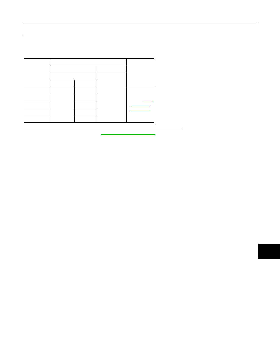
Check voltage between BCM harness connector and ground.
Is the measurement value normal when any of the switches is turned ON?
YES
>> Replace BCM. Refer to
NO
>> Replace the combination switch.
System
Terminals
Voltage
(Approx.)
(+)
(
−
)
BCM
Ground
Connector
Terminal
INPUT 1
M122
107
Refer to
INPUT 2
109
INPUT 3
88
INPUT 4
108
INPUT 5
87