Infiniti EX35. Manual - part 1542


  Index      Infiniti     Infiniti EX35 - service repair manual 2008 year


Search            


Content   ..  1540  1541  1542  1543   ..


Infiniti EX35. Manual - part 1542


WW-20

< FUNCTION DIAGNOSIS >

DIAGNOSIS SYSTEM (IPDM E/R)
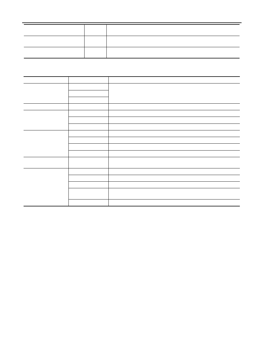
ACTIVE TEST

Test item

HORN CHIRP
[Off/On]

Displays the status of the horn reminder signal received from BCM via CAN com-
munication.

CRNRNG LMP REQ
[Off]

NOTE:
The item is indicated, but not monitored.

Monitor Item

[Unit]

MAIN SIG-

NALS

Description

Test item

Operation

Description

CORNERING LAMP

Off

NOTE:
The item is indicated, but cannot be tested.

LH

RH

HORN

On

Operates horn relay 1 and horn relay 2 for 20 ms.

FRONT WIPER

Off

OFF

Lo

Operates the front wiper relay.

Hi

Operates the front wiper relay and front wiper high relay.

MOTOR FAN

1

OFF

2

Outputs 50% pulse duty signal (PWM signal) to the cooling fan control module.

3

Outputs 80% pulse duty signal (PWM signal) to the cooling fan control module.

4

Outputs 100% pulse duty signal (PWM signal) to the cooling fan control module.

HEAD LAMP WASHER

On

NOTE:
The item is indicated, but cannot be tested.

EXTERNAL LAMPS

Off

OFF

TAIL

Operates the tail lamp relay.

Lo

Operates the headlamp low relay.

Hi

Operates the headlamp low relay and ON/OFF the headlamp high relay at 1 sec-
ond intervals.

Fog

Operates the front fog lamp relay.

WIPER AND WASHER FUSE

WW-21

< COMPONENT DIAGNOSIS >

C

D

E

F

G

H

I

J

K

M

A

B

WW

N

O

P

COMPONENT DIAGNOSIS

WIPER AND WASHER FUSE

Description

INFOID:0000000003138981

Fuse list

Diagnosis Procedure

INFOID:0000000003138982

1.

CHECK FUSES

Check that the following fuses are not fusing.

Is the fuse fusing?

YES

>> Replace the fuse with a new one after repairing the applicable circuit.

NO

>> The fuse is normal.

Unit

Location

Fuse No.

Capacity

Front wiper motor

IPDM E/R

#60

30 A

Washer pump

IPDM E/R

#47

10 A

Unit

Location

Fuse No.

Capacity

Front wiper motor

IPDM E/R

#60

30 A

Washer pump

IPDM E/R

#47

10 A

WW-22

< COMPONENT DIAGNOSIS >

POWER SUPPLY AND GROUND CIRCUIT

POWER SUPPLY AND GROUND CIRCUIT

BCM (BODY CONTROL MODULE)

BCM (BODY CONTROL MODULE) : Diagnosis Procedure

INFOID:0000000003769985

1.

CHECK FUSE AND FUSIBLE LINK

Check that the following fuse and fusible link are not blown.

Is the fuse fusing?

YES

>> Replace the blown fuse or fusible link after repairing the affected circuit if a fuse or fusible link is

blown.

NO

>> GO TO 2.

2.

CHECK POWER SUPPLY CIRCUIT

1.

Turn ignition switch OFF.

2.

Disconnect BCM connectors.

3.

Check voltage between BCM harness connector and ground.

Is the measurement value normal?

YES

>> GO TO 3.

NO

>> Repair harness or connector.

3.

CHECK GROUND CIRCUIT

Check continuity between BCM harness connector and ground.

Does continuity exist?

YES

>> INSPECTION END

NO

>> Repair harness or connector.

IPDM E/R (INTELLIGENT POWER DISTRIBUTION MODULE ENGINE ROOM)

IPDM E/R (INTELLIGENT POWER DISTRIBUTION MODULE ENGINE ROOM) : Di-
agnosis Procedure

INFOID:0000000003769986

1.

CHECK FUSES AND FUSIBLE LINK

Check that the following IPDM E/R fuses or fusible links are not blown.

Signal name

Fuse and fusible link No.

Battery power supply

K

10

Terminals

Voltage

(Approx.)

(+)

(

)

BCM

Ground

Connector

Terminal

M118

1

Battery voltage

M119

11

BCM

Ground

Continuity

Connector

Terminal

M119

13

Existed

POWER SUPPLY AND GROUND CIRCUIT

WW-23

< COMPONENT DIAGNOSIS >

C

D

E

F

G

H

I

J

K

M

A

B

WW

N

O

P

Is the fuse fusing?

YES

>> Replace the blown fuse or fusible link after repairing the affected circuit if a fuse or fusible link is

blown.

NO

>> GO TO 2.

2.

CHECK POWER SUPPLY CIRCUIT

1.

Turn ignition switch OFF.

2.

Disconnect IPDM E/R connector.

3.

Check voltage between IPDM E/R harness connector and ground.

Is the measurement value normal?

YES

>> GO TO 3.

NO

>> Repair harness or connector.

3.

CHECK GROUND CIRCUIT

Check continuity between IPDM E/R harness connectors and ground.

Does continuity exist?

YES

>> INSPECTION END

NO

>> Repair harness or connector.

Signal name

Fuses and fusible link No.

Battery power supply

C

50

51

Terminals

Voltage

(Approx.)

(+)

(

)

IPDM E/R

Connector

Terminal

Ground

E4

1

Battery voltage

IPDM E/R

Ground

Continuity

Connector

Terminal

E5

12

Existed

E6

41


Content   ..  1540  1541  1542  1543   ..