Infiniti EX35. Manual - part 1521


  Index      Infiniti     Infiniti EX35 - service repair manual 2008 year


Search            


Content   ..  1519  1520  1521  1522   ..


Infiniti EX35. Manual - part 1521


WT-40

< COMPONENT DIAGNOSIS >

TIRE PRESSURE WARNING CHECK SWITCH

YES

>> Repair or replace BCM circuit. Replace BCM. Refer to 

BCS-84, "Removal and Installation"

.

NO

>> GO TO 2.

2.

CHECK TIRE PRESSURE WARNING CHECK SWITCH CIRCUIT

1.

Turn the ignition switch OFF.

2.

Disconnect BCM harness connector

3.

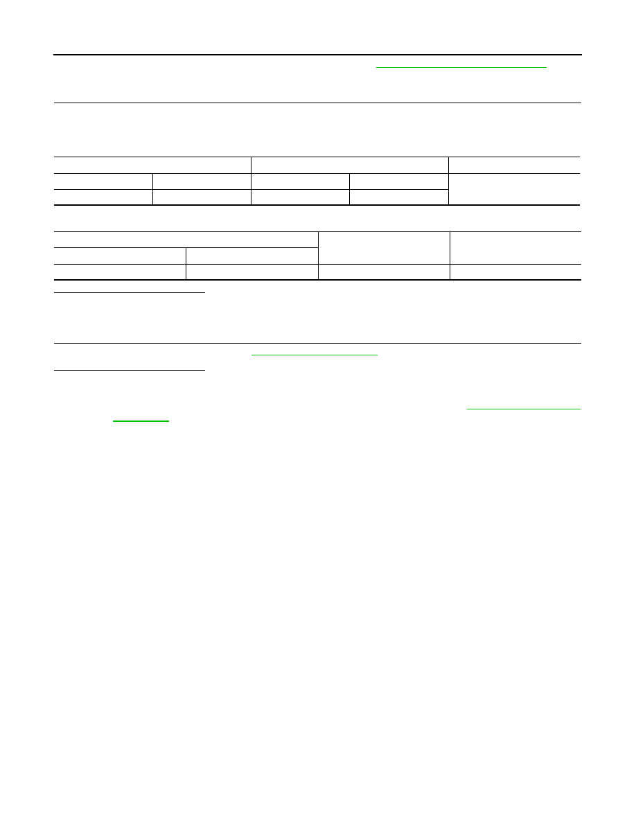
Check continuity between BCM harness connector and tire pressure warning check switch connector.

4.

Check continuity between BCM harness connector and ground.

Is the inspection result normal?

YES

>> GO TO 3.

NO

>> Repair or replace damaged parts.

3.

CHECK BCM

Check BCM input/output signal. Refer to 

WT-48, "Reference Value"

.

Is the inspection result normal?

YES

>> INSPECTION END

NO

>> Check BCM pin terminals for damage or loose connection with harness connector. If any items

are damaged, repair or replace damaged parts. Replace BCM. Refer to 

BCS-84, "Removal and

Installation"

.

BCM

Tire pressure warning check switch

Continuity

Connector

Terminal

Connector

Terminal

Existed

M123

149

M23

1

BCM

Continuity

Connector

Terminal

M123

149

Ground

Not existed

LOW TIRE PRESSURE WARNING LAMP

WT-41

< COMPONENT DIAGNOSIS >

C

D

F

G

H

I

J

K

L

M

A

B

WT

N

O

P

LOW TIRE PRESSURE WARNING LAMP

Description

INFOID:0000000003579744

The combination meter receives tire pressure status from the unified
meter and A/C amp. via CAN communication.
When BCM judges from a transmitter signal that tire pressure is
insufficient, BCM transmits a signal to unified meter and A/C amp.
via CAN communication. unified meter and A/C amp. turns on the
low tire pressure warning lamp mounted on the combination meter.

NOTE: Standard air pressure is for 230 kPa (2.3 kg/cm

2

, 33 psi) vehicles.

Component Function Check

INFOID:0000000003579745

1.

CHECK LOW TIRE PRESSURE WARNING LAMP

Check if low tire pressure warning lamp blinks for 1 second and then goes off after turning the ignition switch
ON.

Is inspection result normal?

YES

>> INSPECTION END

NO

>> Proceed to diagnosis procedure. Refer to 

WT-41, "Diagnosis Procedure"

.

Diagnosis Procedure

INFOID:0000000003579746

1.

CHECK SELF DIAGNOSTIC RESULTS

Perform self-diagnosis of tire pressure monitoring system.
Is inspection result normal?

YES

>> GO TO 2.

NO

>> Check the DTC.

2.

CHECK LOW TIRE PRESSURE WARNING LAMP

Check if low tire pressure warning lamp blinks 1 second and then goes off after turning the ignition switch ON.
Is inspection result normal?

YES

>> INSPECTION END

NO

>> Check combination meter.

SEIA0434E

Condition

Low tire pressure warning lamp

Ignition switch OFF

OFF

Ignition switch ON

Warning lamp turns on for 1second, then turns off.

Less than 182.7 kPa (1.9 kg/cm

2

, 26 psi) [NOTE]

ON

Tire pressure monitoring system malfunction [Other diagnostic item]

Warning lamp blinks 1 min, then turns on.

WT-42

< COMPONENT DIAGNOSIS >

POWER SUPPLY AND GROUND CIRCUIT

POWER SUPPLY AND GROUND CIRCUIT

BCM (BODY CONTROL MODULE)

BCM (BODY CONTROL MODULE) : Diagnosis Procedure

INFOID:0000000003773753

1.

CHECK FUSE AND FUSIBLE LINK

Check that the following fuse and fusible link are not blown.

Is the fuse fusing?

YES

>> Replace the blown fuse or fusible link after repairing the affected circuit if a fuse or fusible link is

blown.

NO

>> GO TO 2.

2.

CHECK POWER SUPPLY CIRCUIT

1.

Turn ignition switch OFF.

2.

Disconnect BCM connectors.

3.

Check voltage between BCM harness connector and ground.

Is the measurement value normal?

YES

>> GO TO 3.

NO

>> Repair harness or connector.

3.

CHECK GROUND CIRCUIT

Check continuity between BCM harness connector and ground.

Does continuity exist?

YES

>> INSPECTION END

NO

>> Repair harness or connector.

UNIFIED METER AND A/C AMP.

UNIFIED METER AND A/C AMP. : Diagnosis Procedure

INFOID:0000000003773754

1.

CHECK FUSE

Check for blown fuses.

Signal name

Fuse and fusible link No.

Battery power supply

K

10

Terminals

Voltage

(Approx.)

(+)

(

)

BCM

Ground

Connector

Terminal

M118

1

Battery voltage

M119

11

BCM

Ground

Continuity

Connector

Terminal

M119

13

Existed

Power source

Fuse No.

Battery

6

Ignition switch ACC or ON

19

Ignition switch ON or START

3

POWER SUPPLY AND GROUND CIRCUIT

WT-43

< COMPONENT DIAGNOSIS >

C

D

F

G

H

I

J

K

L

M

A

B

WT

N

O

P

Is the inspection result normal?

YES

>> GO TO 2.

NO

>> Be sure to eliminate cause of malfunction before installing new fuse.

2.

CHECK POWER SUPPLY CIRCUIT

Check voltage between unified meter and A/C amp. harness connector and ground.

Is the inspection result normal?

YES

>> GO TO 3.

NO

>> Check harness between unified meter and A/C amp. and fuse.

3.

CHECK GROUND CIRCUIT

1.

Turn ignition switch OFF.

2.

Disconnect unified meter and A/C amp. connector.

3.

Check continuity between unified meter and A/C amp. harness connector and ground.

Is the inspection result normal?

YES

>> INSPECTION END

NO

>> Repair harness or connector.

Terminals

Ignition switch position

Value (Approx.)

(+)

(-)

Unified meter A/C amp.

Terminal

Signal name

M67

54

Battery power supply

Ground

OFF

Battery voltage

41

ACC power supply

ACC

Battery voltage

53

Ignition signal

ON

Battery voltage

Unified meter A/C amp.

Ground

Continuity

Connector

Terminal

M67

55

Existed

71

Existed


Content   ..  1519  1520  1521  1522   ..