Content .. 1518 1519 1520 1521 ..
Infiniti EX35. Manual - part 1520
WT-36
< COMPONENT DIAGNOSIS >
TIRE PRESSURE RECEIVER
TIRE PRESSURE RECEIVER
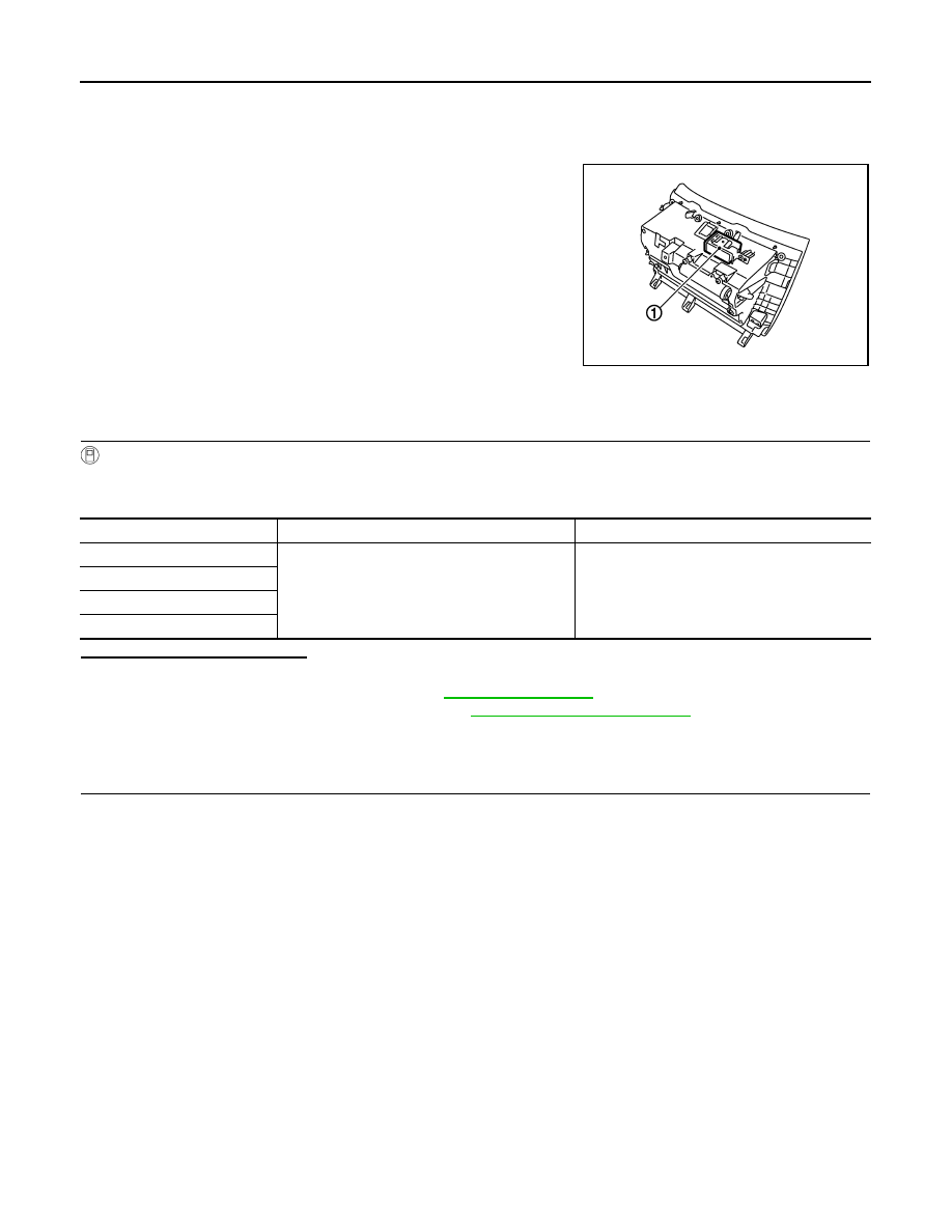
Description
INFOID:0000000003579738
The tire pressure receiver (1) receives the air pressure signal trans-
mitted by the transmitter in each wheel.
Component Function Check
INFOID:0000000003579739
1.
TIRE PRESSURE MONITORING SYSTEM OPERATION
With CONSULT-III
1.
Drive at a speed 40 km/h (25 MPH) or more for 10 minutes.
2.
Check tire pressure with CONSULT-III “DATA MONITOR” within 5 minutes.
Is the inspection result normal?
YES
>> INSPECTION END
NO-1
>> Perform BCM self-diagnosis. Refer to
.
NO-2
>> Proceed to diagnosis procedure. Refer to
Diagnosis Procedure
INFOID:0000000003579740
1.
CHECK TIRE PRESSURE RECEIVER SIGNAL
1.
Turn the ignition switch ON.
CAUTION:
Never start the engine.
2.
Check tire pressure receiver connector and ground signal with oscilloscope.
JPEIC0056ZZ
Monitored item
Condition
Display value
AIR PRESS FL
Start engine and drive at a 40 km/h (25MPH) or
more for 10 minutes.
Approximately equal to the indication on vehicle
information display.
AIR PRESS FR
AIR PRESS RR
AIR PRESS RL