Infiniti EX35. Manual - part 1482


  Index      Infiniti     Infiniti EX35 - service repair manual 2008 year


Search            


Content   ..  1480  1481  1482  1483   ..


Infiniti EX35. Manual - part 1482


VTL-46

< ON-VEHICLE REPAIR >

HEATER CORE

Removal and Installation

INFOID:0000000003545423
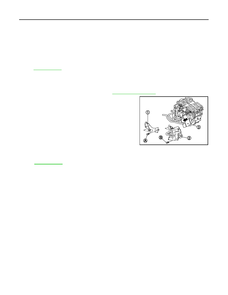
REMOVAL

1.

Remove heater & cooling unit assembly. Refer to 

VTL-36, "Exploded View"

.

2.

Remove mounting screws (A), and then remove heater pipe
cover (1).

3.

Remove mounting screws (B), and then remove foot duct (left)
(2).

4.

Slide heater core (3) to leftward (as shown in the figure).

INSTALLATION

Installation is basically the reverse order of removal.
NOTE:
Refer to 

CO-8, "Refilling"

 when filling radiator with engine coolant.

37. J-nut

38.

Front heater duct

39.

Aspirator hose

40. Aspirator

41.

Foot duct (left)

42.

Defroster door (left)

43. Packing

44.

Center case

45.

Foot door (left)

46. Rear ventilator door

47.

Foot door (right)

48.

J-nut

49. Max. cool door lever

50.

Defroster door lever

51.

Defroster door link

52. Max. cool door link

53.

Intake sensor

54.

Intake sensor bracket

55. Air mix door motor (passenger side)

56.

Air mix door adapter

57.

Heater & cooling unit case (right)

58. Max. cool door (right)

59.

Max. cool door (left)

60.

Air mix door (Slide door)

*With left and right ventilation temperature separately system.

Refer to 

GI-4, "Components"

 for symbols in the figure.

JSIIA0017GB

DUCT AND GRILLE

VTL-47

< ON-VEHICLE REPAIR >

C

D

E

F

G

H

J

K

L

M

A

B

VTL

N

O

P

DUCT AND GRILLE

CENTER VENTILATOR GRILLE

CENTER VENTILATOR GRILLE : Exploded View

INFOID:0000000003545424

CENTER VENTILATOR GRILLE : Removal and Installation

INFOID:0000000003545425

REMOVAL

1.

Remove ventilator ducts (left and right). Refer to 

VTL-50, "VENTILATOR DUCT : Exploded View"

.

2.

Remove mounting screws, and then remove center ventilator
grilles (1) (left and right).

INSTALLATION

Installation is basically the reverse order of removal.

1.

Side defroster duct (front pillar gar-
nish) (right)

2.

Side defroster nozzle (right)

3.

Defroster nozzle

4.

Side defroster nozzle (left)

5.

Side defroster duct (front pillar gar-
nish) (left)

6.

Ventilator duct (left)

7.

Front defroster grille (left)

8.

Instrument panel assembly

9.

Side ventilator grille (left)

10. Center ventilator grille (left)

11. Center ventilator grille (right)

12. Side ventilator grille (right)

13. Front defroster grille (right)

14. Ventilator duct (right)

15. Adaptor duct

JPIIA0667ZZ

JPIIA0668ZZ

VTL-48

< ON-VEHICLE REPAIR >

DUCT AND GRILLE

SIDE VENTILATOR GRILLE

SIDE VENTILATOR GRILLE : Exploded View

INFOID:0000000003545426

SIDE VENTILATOR GRILLE : Removal and Installation

INFOID:0000000003545427

REMOVAL

1.

Remove ventilator ducts (left and right). Refer to 

VTL-50, "VENTILATOR DUCT : Exploded View"

.

2.

Remove mounting screws, and then remove side ventilator
grilles (1) (left and right).

INSTALLATION

Installation is basically the reverse order of removal.

FRONT DEFROSTER GRILLE

1.

Side defroster duct (front pillar gar-
nish) (right)

2.

Side defroster nozzle (right)

3.

Defroster nozzle

4.

Side defroster nozzle (left)

5.

Side defroster duct (front pillar gar-
nish) (left)

6.

Ventilator duct (left)

7.

Front defroster grille (left)

8.

Instrument panel assembly

9.

Side ventilator grille (left)

10. Center ventilator grille (left)

11. Center ventilator grille (right)

12. Side ventilator grille (right)

13. Front defroster grille (right)

14. Ventilator duct (right)

15. Adaptor duct

JPIIA0667ZZ

JPIIA0669ZZ

DUCT AND GRILLE

VTL-49

< ON-VEHICLE REPAIR >

C

D

E

F

G

H

J

K

L

M

A

B

VTL

N

O

P

FRONT DEFROSTER GRILLE : Exploded View

INFOID:0000000003545428

FRONT DEFROSTER GRILLE : Removal and Installation

INFOID:0000000003545429

REMOVAL

Remove front defroster grilles (1), using remover tools (A).

INSTALLATION

Installation is basically the reverse order of removal.

VENTILATOR DUCT

1.

Side defroster duct (front pillar gar-
nish) (right)

2.

Side defroster nozzle (right)

3.

Defroster nozzle

4.

Side defroster nozzle (left)

5.

Side defroster duct (front pillar gar-
nish) (left)

6.

Ventilator duct (left)

7.

Front defroster grille (left)

8.

Instrument panel assembly

9.

Side ventilator grille (left)

10. Center ventilator grille (left)

11. Center ventilator grille (right)

12. Side ventilator grille (right)

13. Front defroster grille (right)

14. Ventilator duct (right)

15. Adaptor duct

JPIIA0667ZZ

JPIIA0672ZZ


Content   ..  1480  1481  1482  1483   ..