Content .. 1425 1426 1427 1428 ..
Infiniti EX35. Manual - part 1427
TM-96
< COMPONENT DIAGNOSIS >
[5AT: RE5R05A]
SHIFT LOCK SYSTEM
YES
>> Go to
NO
>> GO TO 2.
2.
CHECK A/T SHIFT LOCK OPERATION (STEP 2)
Attempt to shift the selector lever to any other position with the brake pedal depressed.
Can the selector lever be shifted to any other position?
YES
>> INSPECTION END
NO
>> Go to
Diagnosis Procedure
INFOID:0000000003130566
1.
CHECK A/T POSITION
Check A/T position. Refer to
TM-153, "2WD : Inspection and Adjustment"
(AWD).
Is the inspection result normal?
YES
>> GO TO 2.
NO
>> Adjust A/T position. Refer to
TM-153, "2WD : Inspection and Adjustment"
(AWD).
2.
CHECK POWER SOURCE
1.
Turn ignition switch OFF.
2.
Disconnect shift lock relay.
3.
Check voltage between shift lock relay vehicle side harness connector terminal and ground.
Is the inspection result normal?
YES
>> GO TO 7.
NO-1
>> When depressing the brake pedal, the voltage is 0 V: GO TO 3.
NO-2
>> When releasing the brake pedal, the voltage is battery voltage: GO TO 5.
3.
CHECK POWER SOURCE
1.
Disconnect stop lamp switch connector.
2.
Check voltage between stop lamp switch vehicle side harness connector terminal and ground.
Is the inspection result normal?
YES
>> GO TO 4.
NO
>>
Check the following. If NG, repair or replace damaged parts.
• 10 A fuse [No. 7, located in the fuse block (J/B)]
• Harness for short to ground or open between battery and stop lamp switch vehicle side harness
connector terminal 3.
• Harness for short to ground or open between battery and stop lamp switch vehicle side harness
connector terminal 1.
• Harness for short to ground between battery and ICC brake hold relay vehicle side harness con-
nector terminal 3. (With ICC)
4.
CHECK STOP LAMP SWITCH
Check stop lamp switch. Refer to
TM-99, "Component Inspection (Stop lamp switch)"
.
Is the inspection result normal?
YES
>>
Check the following. If NG, repair or replace damaged parts.
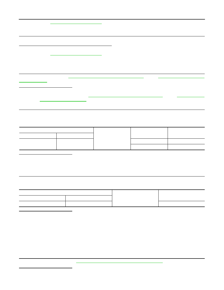
Shift lock relay vehicle side harness connector
Ground
Condition
Voltage (Approx.)
Connector
Terminal
E52
2
Depressed brake pedal.
Battery voltage
Released brake pedal.
0 V
Stop lamp switch vehicle side harness connector
Ground
Voltage (Approx.)
Connector
Terminal
E110
3
Battery voltage