Content .. 1409 1410 1411 1412 ..
Infiniti EX35. Manual - part 1411
TM-32
< FUNCTION DIAGNOSIS >
[5AT: RE5R05A]
SHIFT MECHANISM
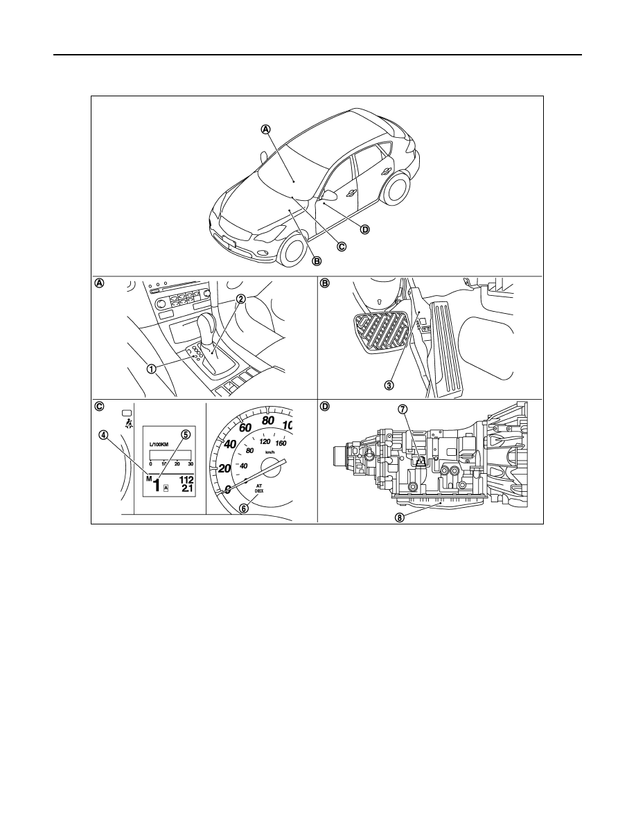
Component Parts Location
INFOID:0000000003508908
*: Control valve with TCM is included in A/T assembly.
NOTE:
• The following components are included in control device assembly (2).
- Manual mode select switch
- Manual mode position select switch
- Shift position switch
• The following components are included in control valve with TCM (8).
- TCM
- Turbine revolution sensor 1, 2
- Revolution sensor
- A/T fluid temperature sensor 1, 2
- PNP switch
- Line pressure solenoid valve
- Torque converter clutch solenoid valve
- Direct clutch solenoid valve
1.
Selector lever position indicator
2.
Control device assembly
3.
Accelerator pedal position sensor
4.
Manual mode indicator
5.
Shift position indicator
6.
A/T CHECK indicator lamp
7.
A/T assembly harness connector
8.
Control valve with TCM*
A.
Center console
B.
Accelerator pedal
C.
Combination meter
D.
A/T assembly
JPDIA0670ZZ