Infiniti EX35. Manual - part 1329


  Index      Infiniti     Infiniti EX35 - service repair manual 2008 year


Search            


Content   ..  1327  1328  1329  1330   ..


Infiniti EX35. Manual - part 1329


SN

SONAR SYSTEM

SN-7

< FUNCTION DIAGNOSIS >

C

D

E

F

G

H

I

J

K

L

M

B

A

O

P

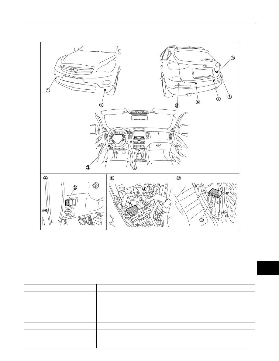
Component Parts Location

INFOID:0000000003160535

Component Description

INFOID:0000000003160536

1.

Corner sensor front RH

2.

Corner sensor front LH

3.

Sonar cancel switch 

4.

Sonar control unit [buzzer (forward) 
integrated]

5.

Corner sensor rear LH

6.

Center sensor rear LH

7.

Center sensor rear RH

8.

Corner sensor rear RH

9.

Buzzer (backward)

A

 Instrument lower panel LH

B.

Cluster lid C removed condition

C.

Luggage side RH

JPNIA0912ZZ

Component

Description

SONAR CONTROL UNIT

• The front warning buzzer is integrated. The warning buzzer outputs by inputting the sensor 

signal from corner/center sensor. The rear warning buzzer outputs the separated buzzer.

• The activation condition is controlled by inputting P range signal, the reverse signal and 

the vehicle speed signal.

• The system turns OFF with sonar cancel switch signal.
• The system setting and the trouble diagnosis is supported with CONSULT-III (K-LINE).

CORNER/CENTER SENSOR

The obstacle distance is detected. The signal is transmitted to the sonar control unit.

BUZZER (BACKWARD)

The warning buzzer outputs with the signal from the sonar control unit. (For rear warning 
buzzer)

SONAR CANCEL SWITCH

The cancel signal is transmitted to the sonar control unit.

SN-8

< FUNCTION DIAGNOSIS >

DIAGNOSIS SYSTEM (SONAR CONTROL UNIT)

DIAGNOSIS SYSTEM (SONAR CONTROL UNIT)

CONSULT-III Function (SONAR)

INFOID:0000000003160537

DESCRIPTION

CONSULT-III can display each diagnostic item using the diagnostic test modes shown as follows:

ECU IDENTIFICATION

Displays the part number of the sonar control unit. 

SELF-DIAGNOSTIC RESULTS

For details, refer to 

SN-38, "DTC Index"

.

DATA MONITOR

Test mode

Function

Ecu Identification

Sonar control unit part number can be read.

Self Diagnostic Results

Sonar control unit checks the conditions and displays memorized error.

Data Monitor

Sonar control unit input/output data in real time.

Active Test

Gives a drive signal to a load to check the operation.

Work support

Changes setting of each function.

Monitor Item

Display

Description

FRONT BUZZER

On

Buzzer (forward) output condition.

Off

Buzzer (forward) non-output condition.

REAR BUZZER

On

Buzzer (backward) output condition.

Off

Buzzer (backward) non-output condition.

 P RANGE

On

Selector lever in P position.

Off

Other than selector lever in P position.

REVERSE RANGE

On

Selector lever in R position.

Off

Other than selector lever in R position.

CANCEL SW

On

When sonar system is ON.

Off

When sonar system is OFF.

CANCEL SW IND

On

When cancel switch indicator lamp is ON.

Off

When cancel switch indicator lamp is OFF.

VHCL SPE COND

On

Turns ON when the vehicle speed is 10 km/h (6.2 MPH) or less while accelerating.

Off

Turns OFF when the vehicle speed is 15 km/h (9.3 MPH) or more while decelerating.

CR SEN [FL]
CR SEN [FR]
CR SEN [RL]
CR SEN [RR]

ERROR

When a sensor is abnormal.

LV.0

When a sensor is not detection.

LV.2

The distance between the corner sensor and an obstacle is 60 cm (23.6 in) or more and 
less then 70 cm (27.5 in).

LV.3

The distance between the corner sensor and an obstacle is 40 cm (15.7 in) or more and 
less then 60 cm (23.6 in).

LV.4

The distance between corner sensor and an obstacle less than 40 cm (15.7 in).

SN

DIAGNOSIS SYSTEM (SONAR CONTROL UNIT)

SN-9

< FUNCTION DIAGNOSIS >

C

D

E

F

G

H

I

J

K

L

M

B

A

O

P

ACTIVE TEST

WORK SUPPORT

CORNER SEN DISTANCE SET

Corner sensor warning buzzer distance can set it to 4 phases as follows.

The default of this model is “FAR”.

CENTER SEN DISTANCE SET

Center sensor warning buzzer distance can set it to 4 phases as follows.

The default of this model is “FAR”.

VOLUME SETTING

CTR SEN [RL]
CTR SEN [RR]

ERROR

When a sensor is abnormal.

LV.0

When a sensor is not detection.

LV.1

The distance between the center sensor and an obstacle is 70 cm (27.5 in) or more and 
less then 110 cm (43.3 in).

LV.2

The distance between the center sensor and an obstacle is 60 cm (23.6 in) or more and 
less then 70 cm (27.5 in).

LV.3

The distance between the center sensor and an obstacle is 40 cm (15.7 in) or more and 
less then 60 cm (23.6 in).

LV.4

The distance between center sensor and an obstacle less than 40 cm (15.7 in).

Monitor Item

Display

Description

Active test item

Function

BUZZER

This test is able to check buzzer (forward/backward) operation.

CANCEL SW

This test is able to check cancel indicator lamp operation. 

SONAR SENSOR

This test is able to check each sonar sensor operation. 

Work support item

Function

CORNER SEN DISTANCE SET

Corner sensor warning buzzer distance is adjustable to 4 phases.

CENTER SEN DISTANCE SET

Center sensor warning buzzer distance is adjustable to 4 phases.

VOLUME SETTING

Warning buzzer volume can set it 2 phases.

TRAILER HITCH MODE

Center sensor (RR, RL) only is adjustable not to detect the distance less than 40 cm (15.7 in).
NOTE:
This adjustment is for preventing to miss detect the distance when installing the trailer hitch.

Warning item

FARTHER

FAR

NORMAL

NEAR

Second stage 
warning

70 – 80 cm (27.5 – 31.4 in)

60 – 70 cm (23.6 – 27.5 in)

50 – 60 cm (19.6 – 23.6 in)

40 – 50 cm (15.7 – 19.6 in)

Third stage 
warning

50 – 70 cm (19.6 – 27.5 in)

40 – 60 cm (15.7 – 23.6 in)

30 – 50 cm (11.8 – 19.6 in)

30 – 40 cm (11.8 – 15.7 in)

Fourth stage 
warning

Less than 50 cm (19.6 in)

Less than 40 cm (15.7 in)

Less than 30 cm (11.8 in)

Less than 30 cm (11.8 in)

Warning item

FARTHER

FAR

NORMAL

NEAR

First stage 
warning

80 – 120 cm (31.4 – 47.2 in)

70 – 110 cm (27.5 – 43.3 in)

60 – 100 cm (23.6 – 39.3 in)

50 – 90 cm (19.6 – 35.4 in)

Second stage 
warning

70 – 80 cm (27.5 – 31.4 in)

60 – 70 cm (23.6 – 27.5 in)

50 – 60 cm (19.6 – 23.6 in)

40 – 50 cm (15.7 – 19.6 in)

Third stage 
warning

50 – 70 cm (19.6 – 27.5 in)

40 – 60 cm (15.7 – 23.6 in)

30 – 50 cm (11.8 – 19.6 in)

30 – 40 cm (11.8 – 15.7 in)

Fourth stage 
warning

Less than 50 cm (19.6 in)

Less than 40 cm (15.7 in)

Less than 30 cm (11.8 in)

Less than 30 cm (11.8 in)

SN-10

< FUNCTION DIAGNOSIS >

DIAGNOSIS SYSTEM (SONAR CONTROL UNIT)

Warning buzzer volume can set it to 2 phases.

TRAILER HITCH MODE

Center sensor (RR, RL) only is adjustable not to detect the distance less than 40 cm (15.7 in).

When installing the trailer hitch

: ON

When not installing the trailer hitch

: OFF


Content   ..  1327  1328  1329  1330   ..