Content .. 1235 1236 1237 1238 ..
Infiniti EX35. Manual - part 1237
GLASS LID
RF-73
< ON-VEHICLE REPAIR >
C
D
E
F
G
H
I
J
L
M
A
B
RF
N
O
P
ON-VEHICLE REPAIR
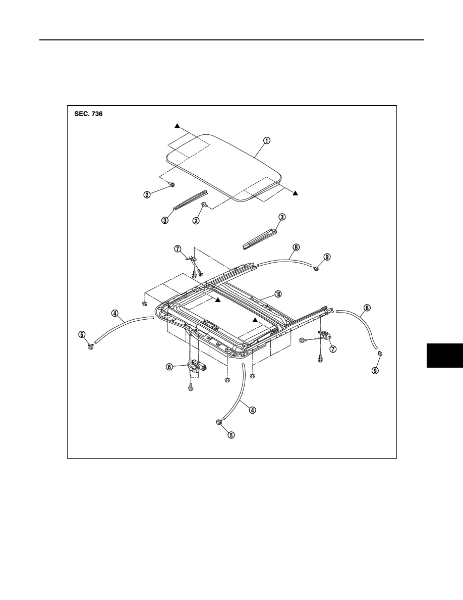
GLASS LID
Exploded View
INFOID:0000000003545364
Removal and Installation
INFOID:0000000003545365
REMOVAL
CAUTION:
Always work with a helper.
1.
Remove the inner blind upper side, and then fold the inner blind so that the TORX bolts can be seen.
1.
Glass lid
2.
TORX bolt
3.
Inner blind (LH/RH)
4.
Drain hose (front)
5.
Drain connector (front)
6.
Sunroof motor assembly
7.
Sunroof bracket (LH/RH)
8.
Drain hose (rear)
9.
Drain connector (rear)
10. Sunroof unit assembly
JMKIA2041ZZ