Infiniti EX35. Manual - part 114
AV
COMPOSITE IMAGE SIGNAL CIRCUIT
AV-237
< COMPONENT DIAGNOSIS >
[BOSE AUDIO WITHOUT NAVIGATION]
C
D
E
F
G
H
I
J
K
L
M
B
A
O
P
COMPOSITE IMAGE SIGNAL CIRCUIT
Description
INFOID:0000000003544789
AV control unit that inputs the camera image signal and AUX image signal transmits the composite image sig-
nal to the display unit.
Diagnosis Procedure
INFOID:0000000003544790
1.
CHECK CONTINUITY COMPOSITE IMAGE SIGNAL CIRCUIT (AV CONTROL UNIT TO DISPLAY UNIT)
1.
Turn ignition switch OFF.
2.
Disconnect AV control unit connector and display unit connector.
3.
Check continuity between AV control unit harness connector and display unit harness connector.
4.
Check continuity between AV control unit harness connector and ground.
Is inspection result normal?
YES
>> GO TO 2.
NO
>> Repair harness or connector.
2.
CHECK COMPOSITE IMAGE SIGNAL (AV CONTROL UNIT TO DISPLAY UNIT)
1.
Connect AV control unit connector and display unit connector.
2.
Turn ignition switch ON.
3.
Check signal between AV control unit harness connector and ground.
Is inspection result normal?
YES
>> Replace display unit.
NO
>> Replace AV control unit.
AV control unit
Display unit
Continuity
Connector
Terminal
Connector
Terminal
M83
36
M71
15
Existed
AV control unit
Ground
Continuity
Connector
Terminal
M83
36
Not existed
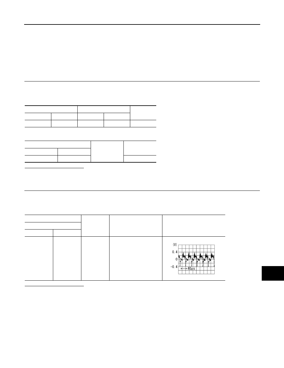
(+)
(
−
)
Condition
Reference value
AV control unit
Connector
Terminal
M83
36
Ground
At rear view camera or AUX
image is displayed.
SKIB2251J