Content .. 1101 1102 1103 1104 ..
Infiniti EX35. Manual - part 1103
MWI-90
< ECU DIAGNOSIS >
UNIFIED METER AND A/C AMP.
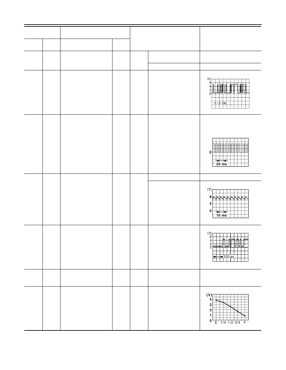
25
(V)
Ground
Manual mode shift down
signal
Input
Ignition
switch
ON
Selector lever down opera-
tion
0 V
Other than the above
12 V
27
(LG)
Ground
Communication signal
(METER
→
AMP.)
Input
Ignition
switch
ON
—
28
(R)
Ground
Vehicle speed signal output
(8-pulse)
Output
Ignition
switch
ON
Speedometer operated
[When vehicle speed is ap-
prox. 40 km/h (25 MPH)]
NOTE:
The maximum voltage varies de-
pending on the specification
(destination unit).
30
(V)
Ground
Parking brake switch signal
Input
Ignition
switch
ON
Parking brake ON
0 V
Parking brake OFF
34
(Y)
Ground
Communication signal
(AMP.
→
LCD)
Output
Ignition
switch
ON
—
41
(V)
Ground
ACC power supply
Input
Ignition
switch
ACC
—
Battery voltage
42
(Y)
Ground
Fuel level sensor signal
Input
Ignition
switch
ON
—
Terminal No.
(Wire color)
Description
Condition
Value
(Approx.)
+
–
Signal name
Input/
Output
SKIA3361E
JSNIA0012GB
JSNIA0007GB
JSNIA0027GB
JSNIA0013GB