Infiniti EX35. Manual - part 1059


  Index      Infiniti     Infiniti EX35 - service repair manual 2008 year


Search            


Content   ..  1057  1058  1059  1060   ..


Infiniti EX35. Manual - part 1059


MA-26

< ON-VEHICLE MAINTENANCE >

CHASSIS MAINTENANCE

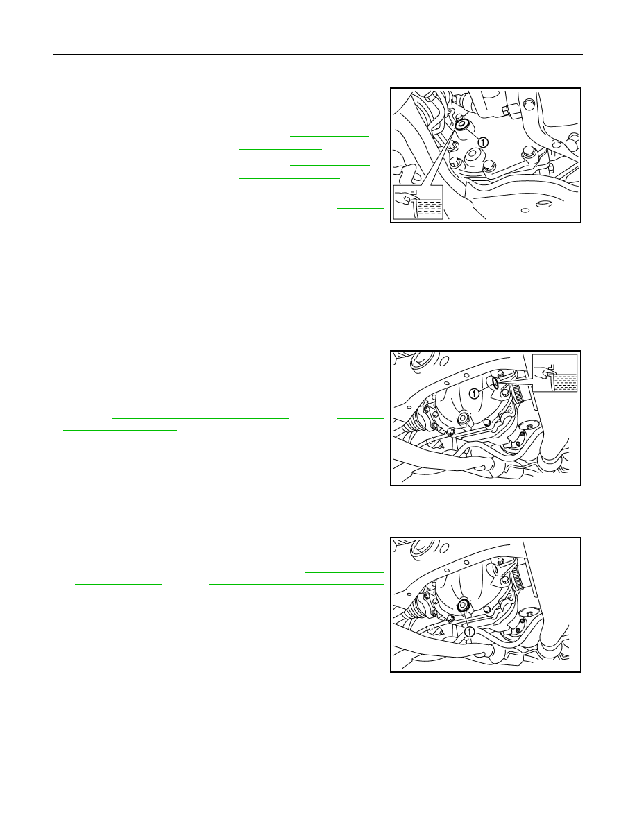
FRONT DIFFERENTIAL GEAR OIL: F160A : Refilling

INFOID:0000000003759983

1.

Remove filler plug (1). Fill with new gear oil until oil level reaches
the specified level near filler plug mounting hole.

2.

After refilling oil, check oil level. Set a gasket to filler plug (1),
then install it to final drive assembly. Refer to 

DLN-108,

"Exploded View"

.

CAUTION:

Never reuse gasket.

REAR DIFFERENTIAL GEAR OIL: R200

REAR DIFFERENTIAL GEAR OIL: R200 : Inspection

INFOID:0000000003759984

OIL LEAKAGE

• Make sure that oil is not leaking from final drive assembly or around it.

OIL LEVEL

• Remove filler plug (1) and check oil level from filler plug mounting

hole as shown in the figure.

CAUTION:

Never start engine while checking oil level.

• Set a gasket on filler plug (1) and install it on final drive assembly.

Refer to 

DLN-163, "2WD : Exploded View"

 (2WD), 

DLN-176,

"AWD : Exploded View"

 (AWD).

CAUTION:

Never reuse gasket.

REAR DIFFERENTIAL GEAR OIL: R200 : Draining

INFOID:0000000003759985

1.

Stop engine.

2.

Remove drain plug (1) and drain gear oil.

3.

Set a gasket on drain plug (1) and install it to final drive assem-
bly and tighten to the specified torque. Refer to 

DLN-163, "2WD

: Exploded View"

 (2WD), 

DLN-176, "AWD : Exploded View"

(AWD).

CAUTION:

Never reuse gasket.

Oil grade and Viscosity

: Refer to 

MA-10, "Fluids 

and Lubricants"

.

Oil capacity

: Refer to 

DLN-133, "Gen-

eral Specifications"

.

JPDID0188ZZ

JPDID0190ZZ

JPDID0191ZZ

CHASSIS MAINTENANCE

MA-27

< ON-VEHICLE MAINTENANCE >

C

D

E

F

G

H

I

J

K

L

M

B

MA

N

O

A

REAR DIFFERENTIAL GEAR OIL: R200 : Refilling

INFOID:0000000003759986

1.

Remove filler plug (1). Fill with new gear oil until oil level reaches
the specified level near filler plug mounting hole.

2.

After refilling oil, check oil level. Set a gasket to filler plug (1),
then install it to final drive assembly. Refer to 

DLN-163, "2WD :

Exploded View"

 (2WD), 

DLN-176, "AWD : Exploded View"

(AWD).

CAUTION:

Never reuse gasket.

WHEELS (BONDING WEIGHT TYPE)

WHEELS (BONDING WEIGHT TYPE) : Adjustment

INFOID:0000000003759987

BALANCING WHEELS (BONDING WEIGHT TYPE)

Preparation Before Adjustment

Using releasing agent, remove double-faced adhesive tape from the road wheel.

CAUTION:

• Be careful not to scratch the road wheel during removal.
• After removing double-faced adhesive tape, wipe clean traces of releasing agent from the road

wheel.

Wheel Balance Adjustment

If a tire balance machine has adhesion balance weight mode settings and drive-in weight mode setting, select
and adjust a drive-in weight mode suitable for road wheels.

1.

Set road wheel on tire balance machine using the center hole as a guide. Start the tire balance machine.

2.

When inner and outer unbalance values are shown on the tire balance machine indicator, multiply outer
unbalance value by 5/3 to determine balance weight that should be used. Select the outer balance weight
with a value closest to the calculated value above and install to the designated outer position of, or at the
designated angle in relation to the road wheel.

CAUTION:

• Do not install the inner balance weight before installing the outer balance weight.
• Before installing the balance weight, be sure to clean the mating surface of the road wheel.

a.

Indicated unbalance value 

×

 5/3 = balance weight to be installed

Calculation example:
23 g (0.81 oz) 

×

 5/3 = 38.33 g (1.35 oz) 

 37.5 g (1.32 oz) bal-

ance weight (closer to calculated balance weight value)
NOTE:
Note that balance weight value must be closer to the calculated
balance weight value.
Example:
36.2 

 35 g (1.23 oz)

36.3 

 37.5 g (1.32 oz)

b.

Installed balance weight in the position.

Oil grade and viscosity

: Refer to 

MA-10, "Fluids 

and Lubricants"

.

Oil capacity

: Refer to 

DLN-207, "Gen-

eral Specification"

.

JPDID0190ZZ

SMA054D

MA-28

< ON-VEHICLE MAINTENANCE >

CHASSIS MAINTENANCE

• When installing balance weight (1) to road wheels, set it into

the grooved area (A) on the inner wall of the road wheel as
shown in the figure so that the balance weight center (B) is
aligned with the tire balance machine indication position
(angle) (C).

CAUTION:

• Always use genuine NISSAN adhesion balance weights.
• Balance weights are non-reusable; always replace with

new ones.

• Do not install more than three sheets of balance weight.

c.

If calculated balance weight value exceeds 50 g (1.76 oz), install
two balance weight sheets in line with each other as shown in
the figure.

CAUTION:

Do not install one balance weight sheet on top of another.

3.

Start the tire balance machine again.

4.

Install drive-in balance weight on inner side of road wheel in the
tire balance machine indication position (angle).

CAUTION:

Do not install more than two balance weight.

5.

Start the tire balance machine. Make sure that inner and outer
residual unbalance values are 5 g (0.17 oz) each or below.

6.

If either residual unbalance value exceeds 5 g (0.17 oz), repeat installation procedures.

TIRE ROTATION

• Follow the maintenance schedule for tire rotation service intervals.

Refer to 

MA-4, "Explanation of General Maintenance"

.

• When installing the wheel, tighten wheel nuts to the specified

torque.

CAUTION:

• Do not include the T-type spare tire when rotating the tires.
• When installing wheels, tighten them diagonally by dividing

the work two to three times in order to prevent the wheels
from developing any distortion.

• Be careful not to tighten wheel nut at torque exceeding the

criteria for preventing strain of disc rotor.

• Use NISSAN genuine wheel nuts for aluminum wheels.

JPEIC0040ZZ

Limit

Dynamic (At flange):

Refer to 

WT-104, "Road Wheel"

.

Static (At flange):

Refer to 

WT-104, "Road Wheel"

.

PEIA0033E

Wheel nuts tighting torque

: Refer to 

WT-104, "Road Wheel"

.

SMA829C

CHASSIS MAINTENANCE

MA-29

< ON-VEHICLE MAINTENANCE >

C

D

E

F

G

H

I

J

K

L

M

B

MA

N

O

A

• Perform the ID registration, after tire rotation. Refer to 

WT-6, "ID REGISTRATION PROCEDURE : Special

Repair Requirement"

.

BRAKE FLUID LEVEL AND LEAKS

BRAKE FLUID LEVEL AND LEAKS : Inspection

INFOID:0000000003134359

• If fluid level is extremely low, check brake system for leaks.

BRAKE LINES AND CABLES

BRAKE LINES AND CABLES : Inspection

INFOID:0000000003134360

• Check brake fluid lines and parking brake cables for improper

attachment, leaks, chafing, abrasions, deterioration, etc.

BRAKE FLUID

BRAKE FLUID : Changing

INFOID:0000000003134361

1.

Drain brake fluid from each bleed valve.

2.

Refill until new brake fluid comes out from each bleed valve.
Use same procedure as in bleeding hydraulic system to refill
brake fluid.
Refer to 

BR-11, "Bleeding Brake System"

.

• Refill with recommended Genuine NISSAN Super Heavy Duty

Brake Fluid or equivalent DOT 3 (US FMVSS No. 116).
Refer to 

MA-10, "Fluids and Lubricants"

.

• Never reuse drained brake fluid.
• Be careful not to splash brake fluid on painted areas.

DISC BRAKE

DISC BRAKE : Inspection

INFOID:0000000003134362

DISC ROTOR

Check condition, wear, and damage.

CALIPER

• Check for leakage.

SBR451D

SBR389C

SBR419C


Content   ..  1057  1058  1059  1060   ..