Infiniti EX35. Manual - part 1057


  Index      Infiniti     Infiniti EX35 - service repair manual 2008 year


Search            


Content   ..  1055  1056  1057  1058   ..


Infiniti EX35. Manual - part 1057


MA-18

< ON-VEHICLE MAINTENANCE >

ENGINE MAINTENANCE

2.

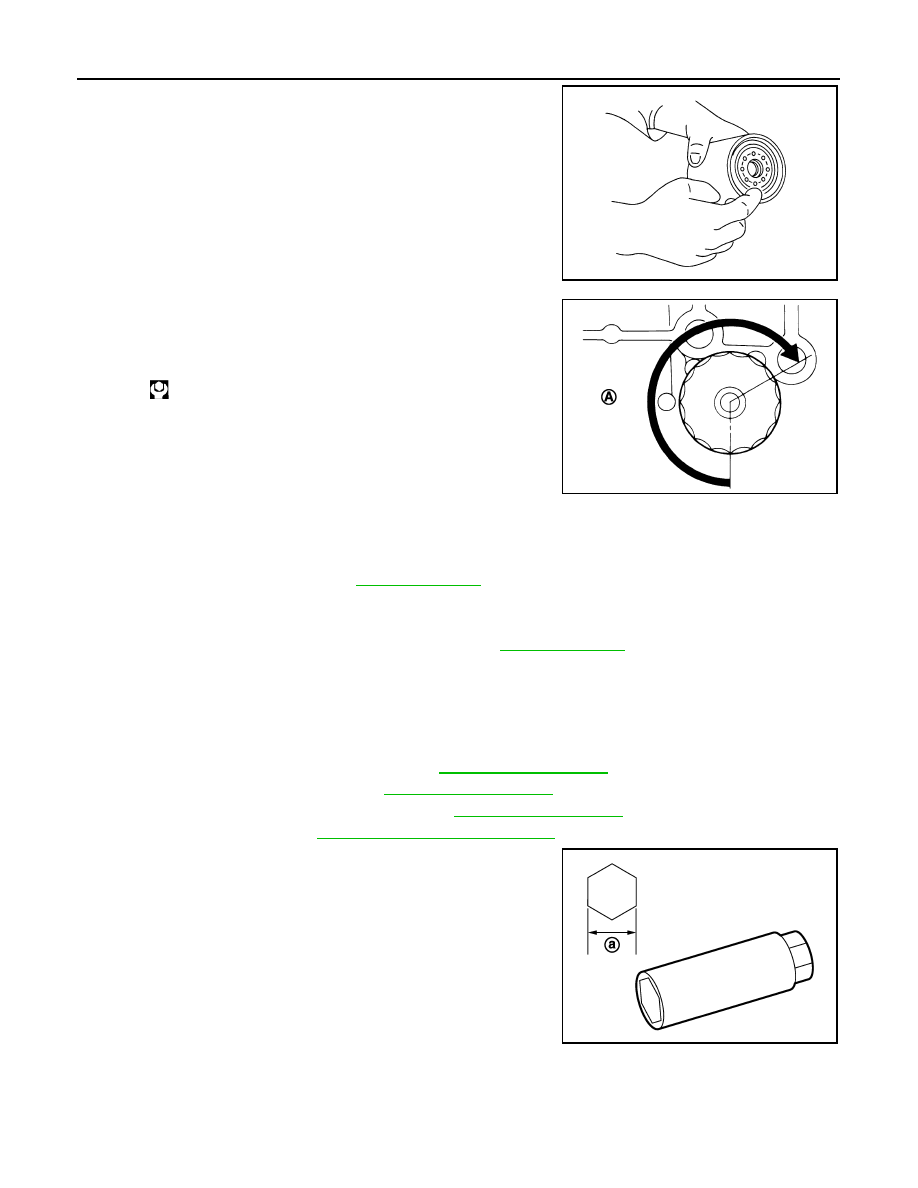
Apply engine oil to the oil seal contact surface of new oil filter.

3.

Screw oil filter manually until it touches the installation surface,
then tighten it by 2/3 turn (A). Or tighten to the specification.

OIL FILTER : Inspection

INFOID:0000000003556583

INSPECTION AFTER INSTALLATION

1.

Check the engine oil level. Refer to 

LU-6, "Inspection"

.

2.

Start the engine, and check there is no leakage of engine oil.

3.

Stop the engine and wait for 10 minutes.

4.

Check the engine oil level, and adjust the level. Refer to 

LU-6, "Inspection"

.

SPARK PLUG

SPARK PLUG : Removal and Installation

INFOID:0000000003556584

REMOVAL

1.

Remove engine cover with power tool. Refer to 

EM-29, "Exploded View"

.

2.

Remove air duct (RH and LH). Refer to 

EM-27, "Exploded View"

.

3.

Remove electric throttle control actuator. Refer to 

EM-32, "Exploded View"

.

4.

Remove ignition coil. Refer to 

EM-47, "Removal and Installation"

.

5.

Remove spark plug with a spark plug wrench (commercial ser-
vice tool).

INSTALLATION

Installation is the reverse order of removal.

SMA010

Oil filter:

: 17.7 N·m (1.8 kg-m, 13 ft-lb)

JPBIA0077ZZ

a

: 14 mm (0.55 in)

JPBIA0030ZZ

ENGINE MAINTENANCE

MA-19

< ON-VEHICLE MAINTENANCE >

C

D

E

F

G

H

I

J

K

L

M

B

MA

N

O

A

SPARK PLUG : Inspection

INFOID:0000000003556589

INSPECTION AFTER REMOVAL

Use the standard type spark plug for normal condition.

CAUTION:

• Never drop or shock spark plug.
• Never use a wire brush for cleaning.
• If plug tip is covered with carbon, spark plug cleaner may be

used.

• Checking and adjusting plug gap is not required between

change intervals.

EVAP VAPOR LINES

EVAP VAPOR LINES : Inspection

INFOID:0000000003134334

1.

Visually inspect EVAP vapor lines for improper attachment and for cracks, damage, loose connections,
chafing and deterioration.

2.

Inspect fuel tank filler cap vacuum relief valve for clogging, sticking, etc.
Refer to 

EC-74, "System Diagram"

.

Spark plug (Standard type)

: Refer to 

EM-140, "Spark Plug"

.

Cleaner air pressure:

Less than 588 kPa (6 kg/cm

2

, 85 

psi)

Cleaning time:

Less than 20 seconds

SMA773C

JPBIA0031ZZ

MA-20

< ON-VEHICLE MAINTENANCE >

CHASSIS MAINTENANCE

CHASSIS MAINTENANCE

EXHAUST SYSTEM

EXHAUST SYSTEM : Inspection

INFOID:0000000003556610

Check exhaust pipes, muffler and mounting for improper attachment,
leakage, cracks, damage or deterioration.
• If anything is found, repair or replace damaged parts.

A/T FLUID

A/T FLUID : Inspection

INFOID:0000000003556611

A/T FLUID LEAKAGE AND A/T FLUID LEVEL CHECK

1.

Warm up engine.

2.

Check for A/T fluid leakage.

3.

Before driving, A/T fluid level can be checked at A/T fluid tem-
peratures of 30 to 50

°

C (86 to 122

°

F) using “COLD” range on A/

T fluid level gauge as follows.

a.

Park vehicle on level surface and set parking brake.

b.

Start the engine and shift the selector lever through each gear
position. Leave selector lever in “P” position.

c.

Check A/T fluid level with engine idling.

d.

Remove A/T fluid level gauge and wipe clean with lint-free
paper.

CAUTION:

When wiping away the A/T fluid level gauge, always use
lint-free paper, not a cloth one.

e.

Re-insert A/T fluid level gauge into A/T fluid charging pipe as far
as it will go.

CAUTION:

Firmly fix the A/T fluid level gauge to the A/T fluid charging
pipe using a stopper attached.

f.

Remove A/T fluid level gauge and note reading. If reading is at
low side of range, add ATF to the A/T fluid charging pipe.

CAUTION:

Do not overfill.

4.

Drive vehicle for approximately 5 minutes in urban areas.

5.

Make the A/T fluid temperature approximately 65

°

C (149

°

F).

NOTE:

SMA211A

SCIA7120E

SMA051D

CHASSIS MAINTENANCE

MA-21

< ON-VEHICLE MAINTENANCE >

C

D

E

F

G

H

I

J

K

L

M

B

MA

N

O

A

A/T fluid level will be greatly affected by temperature as shown in figure. Therefore, be certain to
perform operation while checking data with CONSULT-III.

a.

Select “Data Monitor” mode for “TRANSMISSION”.

b.

Read out the value of “ATF TEMP 1”.

6.

Re-check A/T fluid level at A/T fluid temperatures of approximately 65

°

C (149

°

F) using “HOT” range on A/

T fluid level gauge.

CAUTION:

• When wiping away the A/T fluid level gauge, always use lint-free paper, not a cloth one.
• Firmly fix the A/T fluid level gauge to the A/T fluid charging pipe using a stopper attached.

7.

Install the removed A/T fluid level gauge in the A/T fluid charging pipe.

A/T FLUID CONDITION CHECK

Check the A/T fluid condition.

A/T FLUID : Changing

INFOID:0000000003556621

1.

Warm up ATF.

2.

Stop engine.

3.

Drain ATF from drain plug and refill with new ATF. Always refill same volume with drained ATF.
• To replace the ATF, pour in new ATF at the A/T fluid charging pipe with the engine idling and at the same

time drain the old ATF from the radiator cooler hose return side.

• When the color of the ATF coming out is about the same as the color of the new ATF, the replacement is

complete. The amount of new ATF to use should be 30 to 50% increase of the stipulated amount.

CAUTION:

• If Genuine NISSAN Matic S ATF is not available, Genuine NISSAN Matic J ATF may also be used.

SLIA0016E

Fluid condition

Conceivable cause

Required operation

Varnished (viscous var-
nish state)

Clutch, brake 
scorched

Replace the ATF and check the A/T 
main unit and the vehicle for mal-
functions (wire harnesses, cooler 
pipes, etc.)

Milky white or cloudy

Water in the fluid

Replace the ATF and check for 
places where water is getting in.

Large amount of metal 
powder mixed in

Unusual wear of 
sliding parts within 
A/T

Replace the ATF and check for im-
proper operation of the A/T.

SAT638A

ATF

: Refer to 

TM-269, "General Specification"

.

Fluid capacity

Refer to 

TM-269, "General Specification"

.


Content   ..  1055  1056  1057  1058   ..