Content .. 1049 1050 1051 1052 ..
Infiniti EX35. Manual - part 1051
LU-10
< ON-VEHICLE MAINTENANCE >
OIL FILTER
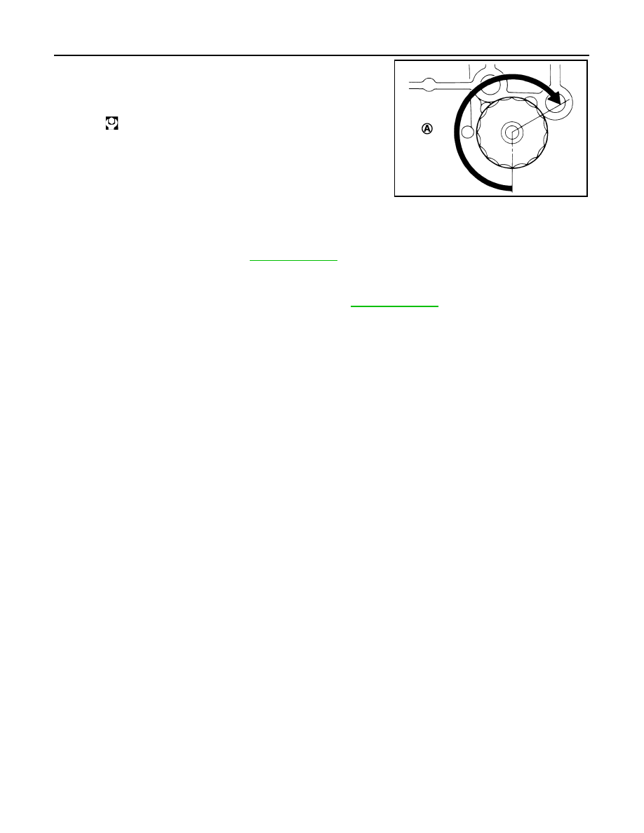
3.
Screw oil filter manually until it touches the installation surface,
then tighten it by 2/3 turn (A). Or tighten to the specification.
Inspection
INFOID:0000000003134529
INSPECTION AFTER INSTALLATION
1.
Check the engine oil level. Refer to
.
2.
Start the engine, and check there is no leakage of engine oil.
3.
Stop the engine and wait for 10 minutes.
4.
Check the engine oil level, and adjust the level. Refer to
.
Oil filter:
: 17.7 N·m (1.8 kg-m, 13 ft-lb)
JPBIA0077ZZ