Infiniti EX35. Manual - part 96
AV
AUXILIARY INPUT JACKS
AV-165
< ON-VEHICLE REPAIR >
[BASE AUDIO WITHOUT NAVIGATION]
C
D
E
F
G
H
I
J
K
L
M
B
A
O
P
AUXILIARY INPUT JACKS
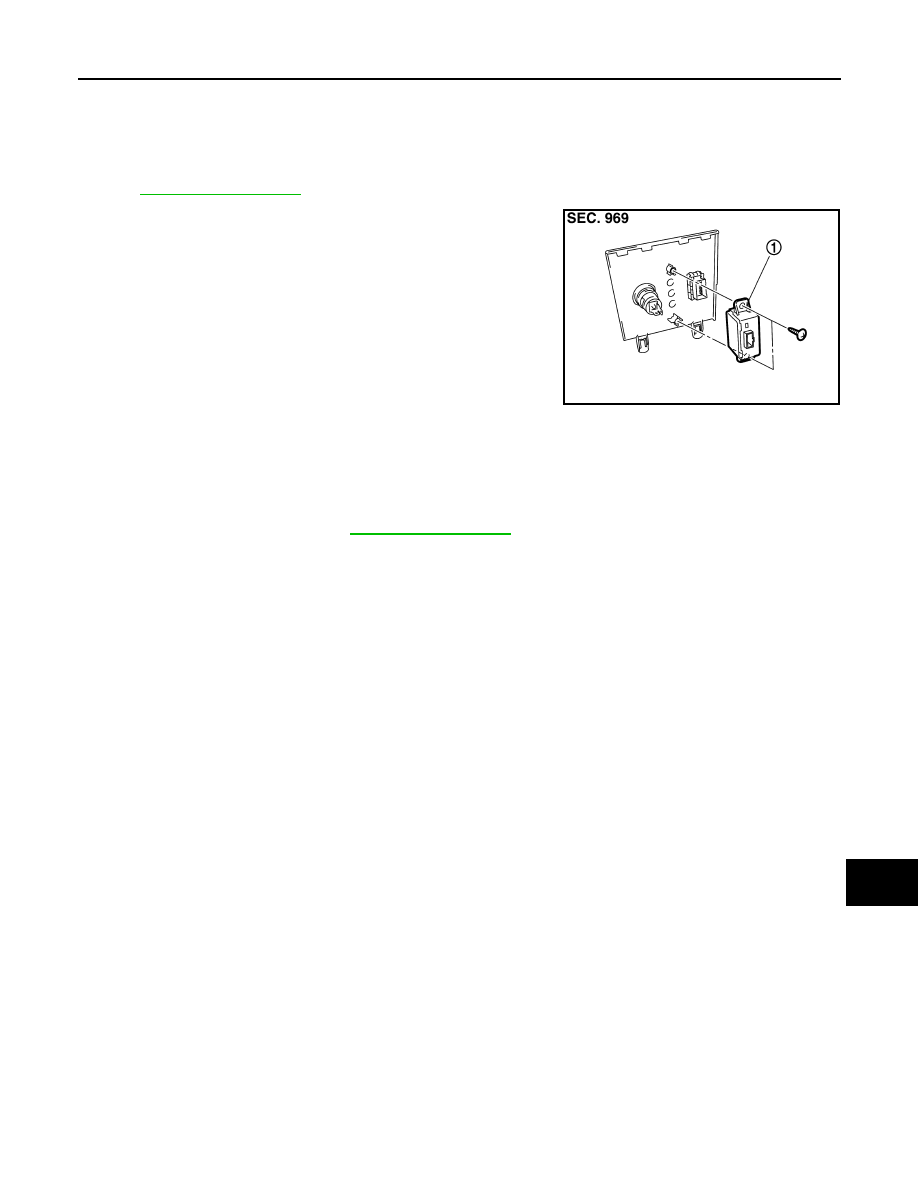
Exploded View
INFOID:0000000003573705
REMOVAL
.
DISASSEMBLY
Removal and Installation
INFOID:0000000003573706
REMOVAL
1.
Remove console finisher. Refer to
2.
Remove auxiliary mounting screws.
3.
Remove auxiliary input jacks.
INSTALLATION
Installation is the reverse order of removal.
JPNIA0882ZZ
1.
Auxiliary input jacks