Infiniti EX35. Manual - part 74
AV
STEERING SWITCH SIGNAL B CIRCUIT
AV-77
< COMPONENT DIAGNOSIS >
[BASE AUDIO WITHOUT NAVIGATION]
C
D
E
F
G
H
I
J
K
L
M
B
A
O
P
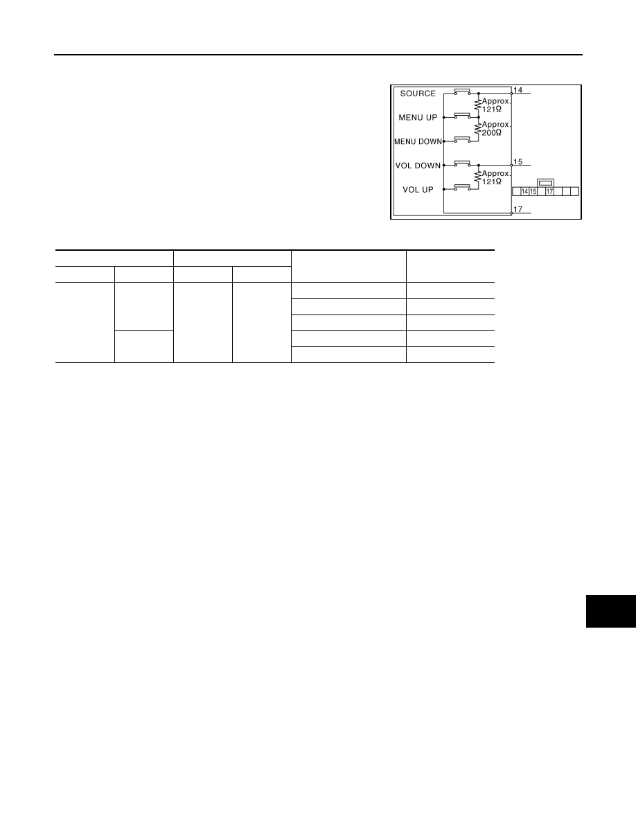
Component Inspection
INFOID:0000000003562718
Measure the resistance between the steering switch connector.
JSNIA0215GB
Steering switch
Steering switch
Condition
Resistance value
(
Ω
)
Connector
Terminals
Connector
Terminal
M303
14
M303
17
SOURCE switch ON
0
MENU UP switch ON
120 – 122
MENU DOWN switch ON
318 – 324
15
VOL DOWN switch ON
0
VOL UP switch ON
120 – 122