Infiniti EX35. Manual - part 73
AV
STEERING ANGLE SENSOR SIGNAL CIRCUIT
AV-73
< COMPONENT DIAGNOSIS >
[BASE AUDIO WITHOUT NAVIGATION]
C
D
E
F
G
H
I
J
K
L
M
B
A
O
P
3.
Turn ignition switch ON.
4.
Check signal between camera control unit harness connector and ground.
Is inspection result normal?
YES
>> INSPECTION END
NO
>> Replace steering angle sensor.
(+)
(
−
)
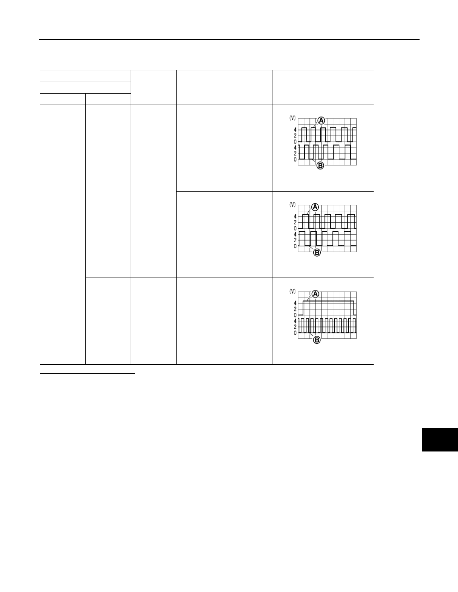
Condition
Reference value
Camera control unit
Connector
Terminals
B50
23, 24
Ground
Turn the steering to the right
A: Sensor signal 1
B: Sensor signal 2
Turn the steering to the left
A: Sensor signal 1
B: Sensor signal 2
25
Ground
Turn the steering around the
neutral position
A: Sensor signal 3
B: Sensor signal 1
SKIB3827E
SKIB3828E
SKIB3829E