Infiniti EX35. Manual - part 70
AV
VERTICAL SYNCHRONIZING (VP) SIGNAL CIRCUIT
AV-61
< COMPONENT DIAGNOSIS >
[BASE AUDIO WITHOUT NAVIGATION]
C
D
E
F
G
H
I
J
K
L
M
B
A
O
P
VERTICAL SYNCHRONIZING (VP) SIGNAL CIRCUIT
Description
INFOID:0000000003508408
In composite image (AUX image, camera image), transmit the vertical synchronizing (VP) signal and horizon-
tal synchronizing (HP) signal from display unit to AV control unit so as to synchronize the RGB images dis-
played with AV control unit such as the image quality adjusting menu, etc.
Diagnosis Procedure
INFOID:0000000003508409
1.
CHECK CONTINUITY VERTICAL SYNCHRONIZING (VP) SIGNAL CIRCUIT
1.
Turn ignition switch OFF.
2.
Disconnect display unit connector and AV control unit connector.
3.
Check continuity between display unit harness connector and AV control unit harness connector.
4.
Check continuity between display unit harness connector and ground.
Is the inspection result normal?
YES
>> GO TO 2.
NO
>> Repair harness or connector.
2.
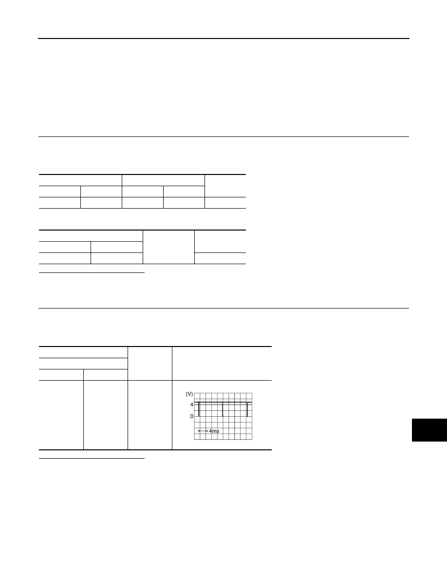
CHECK VERTICAL SYNCHRONIZING (VP) SIGNAL
1.
Connect display unit connector and AV control unit connector.
2.
Turn ignition switch ON.
3.
Check signal between display unit harness connector and ground.
Is the inspection result normal?
YES
>> Replace AV control unit.
NO
>> Replace display unit.
Display unit
AV control unit
Continuity
Connector
Terminal
Connector
Terminal
M71
20
M83
57
Existed
Display unit
Ground
Continuity
Connector
Terminal
M71
20
Not existed
(+)
(
−
)
Reference value
Display unit
Connector
Terminal
M71
20
Ground
SKIB3598E