Infiniti EX35. Manual - part 23


  Index      Infiniti     Infiniti EX35 - service repair manual 2008 year


Search            


Content   ..  21  22  23  24   ..


Infiniti EX35. Manual - part 23


ADP-86

< COMPONENT DIAGNOSIS >

FRONT DOOR SWITCH (DRIVER SIDE)

FRONT DOOR SWITCH (DRIVER SIDE)

Description

INFOID:0000000003134721

Detects front door (driver side) open/close condition.

Component Function Check

INFOID:0000000003134722

1.

CHECK FUNCTION

1.

Turn ignition switch ON.

2.

Select “DOOR SW-DR” in “Data monitor” mode with CONSULT-III.

3.

Check the front door switch (driver side) signal under the following conditions. 

Is the inspection result normal?

YES

>> INSPECTION END

NO

>> Perform diagnosis procedure. Refer to 

ADP-86, "Diagnosis Procedure"

.

Diagnosis Procedure

INFOID:0000000003134723

1.

CHECK FRONT DOOR SWITCH (DRIVER SIDE) SIGNAL

1.

Turn ignition switch OFF.

2.

Disconnect front door switch (driver side) connector.

3.

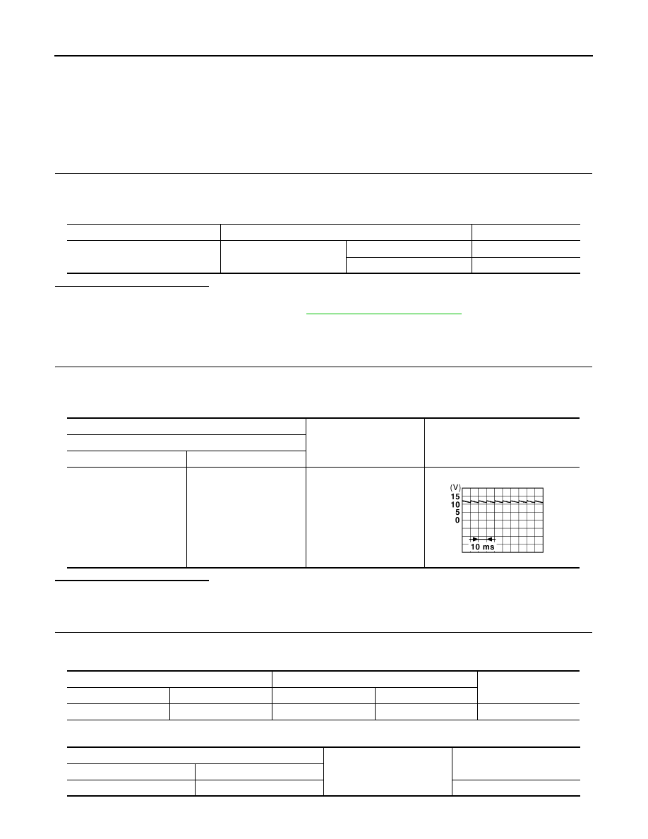
Check signal between front door switch (driver side) connector and ground with oscilloscope.

Is the inspection result normal?

YES

>> GO TO 3.

NO

>> GO TO 2.

2.

CHECK FRONT DOOR SWITCH (DRIVER SIDE) CIRCUIT 

1.

Disconnect BCM connector.

2.

Check continuity between BCM connector and front door switch (driver side) connector.

3.

Check continuity between BCM connector and ground.

Monitor item

Condition

Status

DOOR SW-DR

Front door switch
(driver side)

Open

ON

Close

OFF

(+)

(–)

Voltage (V)

(Approx.)

Front door switch (driver side)

Connector

Terminal

B16

2

Ground

JPMIA0011GB

BCM

Front door switch(driver side)

Continuity 

Connector

Terminal

Connector

Terminal

M123

150

B16 2

Existed

BCM

Ground

Continuity 

Connector

Terminal

M123

150

Not existed

FRONT DOOR SWITCH (DRIVER SIDE)

ADP-87

< COMPONENT DIAGNOSIS >

C

D

E

F

G

H

I

K

L

M

A

B

ADP

N

O

P

Is the inspection result normal?

YES

>> Replace BCM. Refer to 

BCS-84, "Exploded View"

.

NO

>> Repair or replace harness or connector.

3.

CHECK FRONT DOOR SWITCH (DRIVER SIDE) 

Refer to 

ADP-87, "Component Inspection"

.

Is the inspection result normal?

YES

>> GO TO 4.

NO

>> Replace front door switch (driver side). Refer to 

DLK-257, "Removal and Installation"

.

4.

CHECK INTERMITTENT INCIDENT

Refer to 

GI-38, "Intermittent Incident"

.

>> INSPECTION END

Component Inspection

INFOID:0000000003134724

1.

CHECK FRONT DOOR SWITCH (DRIVER SIDE)

1.

Turn ignition switch OFF.

2.

Disconnect front door switch (driver side) connector.

3.

Check continuity between front door switch (driver side) terminals.

Is the inspection result normal?

YES

>> INSPECTION END

NO

>> Replace front door switch (driver side). Refer to 

DLK-257, "Removal and Installation"

.

Front door switch (driver side)

Condition

Continuity

Terminal

2

Ground part of door 

switch

Front door switch
(driver side)

Pushed

Not existed

Released

Existed

ADP-88

< COMPONENT DIAGNOSIS >

SLIDING SENSOR

SLIDING SENSOR

Description

INFOID:0000000003134725

• The sliding sensor is installed to the seat slide cushion frame.
• The pulse signal is inputted to the driver seat control unit when sliding is performed.
• The driver seat control unit counts the pulse and calculates the sliding amount of the seat.

Component Function Check

INFOID:0000000003134726

1.

CHECK FUNCTION

1.

Turn ignition switch ON.

2.

Select “SLIDE PULSE” in “Data monitor” mode with CONSULT-III. 

3.

Check sliding sensor signal under the following conditions.

*1

: The value at the seat position attained when the battery is connected is considered to be 32768.

Is the indication normal?

YES

>> INSPECTION END

NO

>> Perform diagnosis procedure. Refer to 

ADP-88, "Diagnosis Procedure"

.

Diagnosis Procedure

INFOID:0000000003134727

1.

CHECK SLIDING SENSOR SIGNAL

1.

Turn ignition switch ON.

2.

Check voltage signal between driver seat control unit harness connector and ground with oscilloscope.

Is the inspection result normal?

YES

>> Replace driver seat control unit. Refer to 

ADP-209, "Removal and Installation"

.

NO

>> GO TO 2.

2.

CHECK SLIDING SENSOR CIRCUIT

1.

Turn ignition switch OFF.

2.

Disconnect driver seat control unit and sliding sensor connector.

3.

Check continuity between driver seat control unit harness connector and sliding sensor harness connec-
tor.

Monitor item

Condition

Valve

SLIDE PULSE

Seat sliding

Operate (forward)

Change (increase)

*1

Operate (backward)

Change (decrease)

*1

Release

No change

*1

(+)

(–)

Condition

Voltage (V)

(Approx.)

Driver seat control unit

Connector

Terminal

B451

24

Ground

Seat sliding

Operate

Other than 
above

0 or 5

JMJIA0119ZZ

SLIDING SENSOR

ADP-89

< COMPONENT DIAGNOSIS >

C

D

E

F

G

H

I

K

L

M

A

B

ADP

N

O

P

4.

Check continuity between driver seat control unit harness connector and ground.

Is the inspection result normal?

YES

>> GO TO 3.

NO

>> Repair or replace harness or connector.

3.

CHECK SLIDING SENSOR POWER SUPPLY

1.

Connect driver seat control unit connector.

2.

Turn ignition switch ON.

3.

Check voltage between sliding sensor harness connector and ground.

Is the inspection result normal?

YES

>> GO TO 5.

NO

>> GO TO 4.

4.

CHECK SLIDING SENSOR POWER SUPPLY CIRCUIT 

1.

Turn ignition switch OFF.

2.

Disconnect driver seat control unit connector.

3.

Check continuity between driver seat control unit harness connector and sliding sensor harness connec-
tor.

4.

Check continuity between driver seat control unit harness connector and ground.

Is the inspection result normal?

YES

>> Replace driver seat control unit. Refer to 

ADP-209, "Removal and Installation"

.

NO

>> Repair or replace harness or connector.

5.

CHECK SLIDING SENSOR GROUND 

1.

Turn ignition switch OFF.

2.

Disconnect driver seat control unit connector.

3.

Check continuity between driver seat control unit harness connector and sliding sensor harness connec-
tor.

Driver seat control unit

Sliding sensor

Continuity

Connector

Terminal

Connector

Terminal

B451

24

B453

24

Existed

Driver seat control unit

Ground

Continuity 

Connector

Terminal

B451

24

Not existed

(+)

(–)

Voltage (V)

(Approx.)

Sliding sensor

Connector

Terminal

B453

16

Ground

Battery voltage

Driver seat control unit

Sliding sensor

Continuity

Connector

Terminal

Connector

Terminal

B451

16

B453

16

Existed

Driver seat control unit 

Ground

Continuity 

Connector

Terminal

B451

16

Not existed

Driver seat control unit

Sliding sensor

Continuity

Connector

Terminal

Connector

Terminal

B451

31

B453

31

Existed


Content   ..  21  22  23  24   ..