Infiniti EX35. Manual - part 6


  Index      Infiniti     Infiniti EX35 - service repair manual 2008 year


Search            


Content   ..  4  5  6  7   ..


Infiniti EX35. Manual - part 6


ADP-18

< FUNCTION DIAGNOSIS >

AUTOMATIC DRIVE POSITIONER SYSTEM

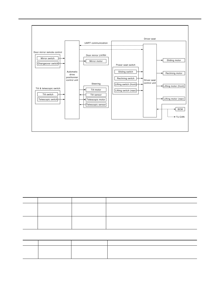
MANUAL FUNCTION : System Diagram

INFOID:0000000003134619

MANUAL FUNCTION : System Description

INFOID:0000000003134620

OUTLINE

The driving position (seat, steering column and door mirror position) can be adjusted manually with power seat
switch, tilt & telescopic switch and door mirror remote control switch.

OPERATION PROCEDURE

1.

Turn ignition switch ON.

2.

Operate power seat switch, tilt & telescopic switch or door mirror remote control switch.

3.

The driver seat, steering column or door mirror operates according to the operation of each switch.

DETAIL FLOW

Seat

Tilt & Telescopic

JMJIA0114GB

Order

Input

Output

Control unit condition

1

Power seat switch
(sliding, lifting, reclin-
ing)

The power seat switch signal is inputted to the driver seat control 
unit when the power seat switch is operated.

2

Motors
(sliding, lifting, reclin-
ing)

The driver seat control unit outputs signals to each motor accord-
ing to the power seat switch input signal.

Order

Input

Output

Control unit condition

1

Tilt & telescopic switch

The tilt & telescopic switch signal is inputted to the automatic 
drive positioner control unit when the tilt & telescopic switch is op-
erated.

AUTOMATIC DRIVE POSITIONER SYSTEM

ADP-19

< FUNCTION DIAGNOSIS >

C

D

E

F

G

H

I

K

L

M

A

B

ADP

N

O

P

*: Tilt does not operates upward when tilt sensor volume is less than 1.2 V, tilt does not operate downward when the sensor value is big-
ger than 3.4 V. Telescopic does not operates backward when telescopic sensor value is less than 0.8 V, telescopic does not operate for-
ward when the sensor value is bigger than 3.4 V.

Door Mirror

NOTE:
The door mirrors can be operated manually when ignition switch is in either ACC or ON position. The ignition
switch signal (ACC/ON) is transmitted from BCM to the driver seat control unit via CAN communication and
from the driver seat control unit to the automatic drive positioner control unit via UART communication.

2

Motors
(Tilt, telescopic)

The automatic drive positioner control unit actuates each motor 
according to the operation of the tilt & telescopic switch.

3

Sensors
(Tilt, telescopic)

The automatic drive positioner control unit recognizes any oper-
ation limit of each actuator via each sensor and will not operate 
the actuator anymore at that time.*

Order

Input

Output

Control unit condition

Order

Input

Output

Control unit condition

1

Door mirror remote 
control switch

The door mirror remote control switch signal is inputted to the au-
tomatic drive positioner control unit when the door mirror remote 
control switch is operated.

2

Motors
(Door mirror motor)

The automatic drive positioner control unit actuates each motor 
according to the operation of the door mirror remote control switch.

ADP-20

< FUNCTION DIAGNOSIS >

AUTOMATIC DRIVE POSITIONER SYSTEM

MANUAL FUNCTION : Component Parts Location

INFOID:0000000003586963

1.

BCM M118, M119, M122, M123

2.

Automatic drive positioner control unit 
M51, M52

3.

Tilt motor M49

4.

Telescopic motor M49

5.

Unified meter and A/C amp. M67

6.

AV control unit
With NAVI M87, M88
Without NAVI M83, M85

7.

AT assembly connector F51

8.

Tilt & telescopic switch M31

9.

Key slot M22

10. Tilt sensor M48

11.

Telescopic sensor M48

12. Seat memory switch D5

13. Door mirror remote control switch 

D17

A.

Dash side lower (Passenger side)

B.

View with instrument driver lower 
panel removed

C.

View with steering column cover low-
er and upper removed

D.

Behind cluster lid C

E.

A/T assembly
(TCM is built in A/T assembly)

F.

View with instrument driver lower 
panel removed

G

View with steering column cover low-
er and upper removed

JMJIA1472ZZ

AUTOMATIC DRIVE POSITIONER SYSTEM

ADP-21

< FUNCTION DIAGNOSIS >

C

D

E

F

G

H

I

K

L

M

A

B

ADP

N

O

P

MANUAL FUNCTION : Component Description

INFOID:0000000003134622

CONTROL UNITS

INPUT PARTS

Switches

14. Front door switch (driver side) B16

15. Control device (detention switch) 

M137

16. Sliding, lifting switch

 (Power seat switch B459)

17. Reclining switch (power seat switch 

B459)

18.  Door mirror (driver side) D3

19. Reclining motor B454

20.  Driver seat control unit B451, B452

21. Lifting motor (front) B455

22. Lifting motor (rear) B456

23. Sliding motor B461

24. Sliding sensor B453

H.

View with center console assembly 
removed

I.

View with seat cushion pad and seat-
back pad removed

J.

Backside of the seat cushion

JMJIA1473ZZ

Item

Function

Driver seat control unit

• Operates the specific seat motor with the signal from the power seat switch.
• Transmits the ignition switch signal (ACC/ON) via UART communication to the 

automatic drive positioner control unit.

Automatic drive positioner control unit

Operates the specific motor with the signal from tilt & telescopic switch or door mir-
ror remote control switch.

BCM

Recognizes the following status and transmits it to the driver seat control unit via 
CAN communication.
• Ignition position: ACC/ON

Item

Function

Power seat switch

The following switch is installed.
• Reclining switch
• Lifting switch (front)
• Lifting switch (rear)
• Sliding switch
The specific parts can be operated with the operation of each switch.


Content   ..  4  5  6  7   ..