Honda Ridgeline. Manual - part 591


  Index      Honda     Honda Ridgeline - service repair manual 2006-2008 year


Search            


Content   ..  589  590  591  592   ..


Honda Ridgeline. Manual - part 591


01

02

SJC8A00H46400055411KBAT00

Removal

Installation

24-189

Side Impact Sensor (First) Replacement

A

B

A

C

B
9.8 N·m
(1.0 kgf·m, 7.2 lbf·ft)

1. Disconnect the negative cable from the battery,

then wait 3 minutes before starting work.

2. Disconnect the appropriate side airbag 2P

connector (see step 4 on page 24-25).

3. Remove the seat assembly (see page 20-97).

4. Remove the front door sill trim (see page 20-60)

and the B-pillar lower trim (see page 20-65).

5. Disconnect the floor wire harness 2P connector

from the side impact sensor (first).

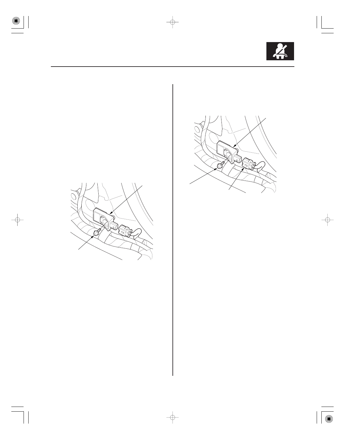
6. Using a TORX T30 bit, remove the TORX bolt (A),

then remove the side impact sensor (first) (B).

1. Install the new side impact sensor (first) (A) with

TORX bolt (B), then connect the floor wire harness
2P connector (C) to the side impact sensor (first).

2. Reconnect the negative cable to the battery.

3. Install all removed parts.

4. After installing the side impact sensor (first),

confirm proper system operation: Turn the ignition
switch ON (II); the SRS indicator should come on
for about 6 seconds and then go off.

03

04

SJC8A00H46400055411KBAT01

Removal

Installation

24-190

SRS

Side Impact Sensor (Second) Replacement

A

B

C

A

C

B
9.8 N·m
(1.0 kgf·m, 7.2 lbf·ft)

1. Disconnect the negative cable from the battery,

then wait 3 minutes before starting work.

2. Disconnect the appropriate side curtain airbag 2P

connector (see step 5 on page 24-25).

3. Remove the rear seat assembly (see page 20-117).

4. Remove the rear seat side trim (see step 9 on page

20-62).

5. Disconnect the floor wire harness 2P connector (A)

from the side impact sensor (second).

6. Using a TORX T30 bit, remove the TORX bolt (B),

then remove the side impact sensor (second) (C).

1. Install the new side impact sensor (second) (A) with

TORX bolt (B), then connect the floor wire harness
2P connector (C) to the side impact sensor (second).

2. Reconnect the negative cable to the battery.

3. Install all removed parts.

4. After installing the side impact sensor (second),

confirm proper system operation: Turn the ignition
switch ON (II); the SRS indicator should come on
for about 6 seconds and then go off.

01

*01

SJC8A0BH46400053795KBAT00

Removal

Installation

24-191

Front Passenger’s Weight Sensor Replacement

A

B

A

C

D

A

D

E

A
14 N·m
(1.4 kgf·m, 10 lbf·ft)

B
59 N·m
(6.0 kgf·m, 44 lbf·ft)

NOTE: Removal of the front passenger’s weight sensors
must be performed according to the precautions/
procedures described at the beginning of the SRS
section (see page 24-17).

1. Disconnect the negative cable from the battery,

then wait 3 minutes before starting work.

2. Remove the front passenger’s seat assembly

(see page 20-97).

3. Remove the tamper-resistant TORX bolts (A)

attaching the seat track (B) and seat riser (C) to the
weight sensors (D).

4. Disconnect the sensor connectors (E) from the ODS

unit harness connectors, then remove the front
passenger’s weight sensors.

NOTE: Be sure to install the harness wires so they are
not pinched or interfering with other parts.

1. Install the new front passenger’s weight sensors

with TORX bolts (A, B) under the seat track.

2. Reinstall the front passenger’s seat (see page

20-97).

3. Reconnect the negative cable to the battery.

4. Calibrate the ODS unit (see page 24-31).

5. After installing the front passenger’s weight

sensors, confirm proper system operation: Turn the
ignition switch ON (II); the SRS indicator should
come for about 6 seconds and then go off.

*01

*02

SJC8A0AH46400043771KBAT00

Removal

Installation

24-192

SRS

OPDS/ODS Unit Replacement

A

D

C

B

E

E

A

D

C

B

1. Disconnect the negative cable from the battery,

then wait 3 minutes before starting work.

2. Disconnect the passenger’s side airbag harness 2P

connector (see step 4 on page 24-25).

3. Remove the passenger’s seat assembly (see page

20-97) and seat-back cover (see page 20-111).

4. Remove the cover (A), then disconnect the OPDS

unit 8P/ODS unit 18P connector (B) and sensor
connectors (C) from the OPDS/ODS unit (D).

5. Remove the two screws (E) and the OPDS/ODS unit.

1. Place the new OPDS/ODS unit (A) on the seat-back

frame. Tighten the two screws (B), and connect the
OPDS unit 8P/ODS unit 18P connector (C) and
sensor connectors (D) to the OPDS/ODS unit.
Reinstall the cover (E).

2. Install the seat-back cover in the reverse order of

removal.

3. Install the seat assembly (see page 20-97), then

connect the side airbag harness 2P connector.

4. Reconnect the negative cable to the battery.

5. Set the seat-back in the normal position, and make

sure there is nothing on the front passenger’s seat.

6. Initialize the OPDS/ODS unit (see page 24-30).

7. After installing the OPDS/ODS unit, confirm proper

system operation: Turn the ignition switch ON (II);
the SRS indicator should come on for about
6 seconds and then go off.


Content   ..  589  590  591  592   ..