Honda Ridgeline. Manual - part 577


  Index      Honda     Honda Ridgeline - service repair manual 2006-2008 year


Search            


Content   ..  575  576  577  578   ..


Honda Ridgeline. Manual - part 577


01

02

YES

NO

YES

NO

24-133

PASSENGER’S SEAT
WIRE HARNESS
3P CONNECTOR

SRS UNIT CONNECTOR B (28P)

ORN

PASSENGER’S SEAT
WIRE HARNESS
3P CONNECTOR

SRS UNIT CONNECTOR B (28P)

BLU

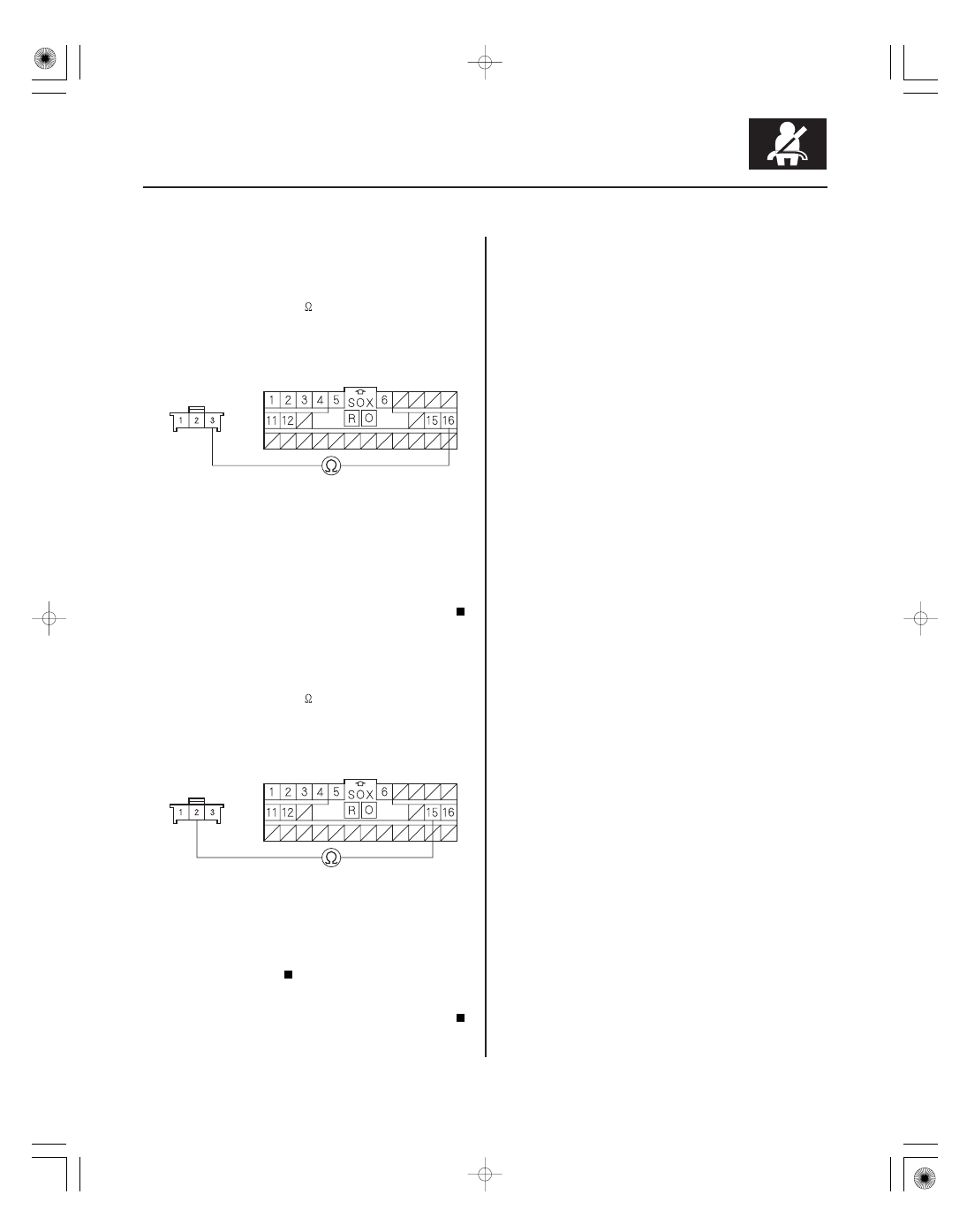
12. Measure the resistance between the No. 16

terminal of SRS unit connector B (28P) and the
No. 3 terminal of the passenger’s seat wire harness
3P connector.
There should be 0

1

.

Go to step 13.

Open in the passenger’s seat wire harness or

the floor wire harness; replace the faulty harness.

13. Measure the resistance between the No. 15

terminal of SRS unit connector B (28P) and the
No. 2 terminal of the passenger’s seat wire harness
3P connector.
There should be 0

1

.

Faulty SRS unit; replace the SRS unit

(see page 24-188).

Open in the passenger’s seat wire harness or

the floor wire harness; replace the faulty harness.

Wire side of female terminals

Wire side of female terminals

Is the r esistance as specif ied?

Is the r esistance as specif ied?

01

02

SJC8A00K791000R622XFAAT00

DTC 62-2x (‘‘x’’ can be 0 thru 9 or A thru F):

YES

NO

YES

NO

24-134

SRS

DTC Troubleshooting (cont’d)

A

FRONT PASSENGER’S SEAT BELT
BUCKLE SWITCH 3P CONNECTOR

BLU

BLK

BLK

GRY

Short in Front Passenger’s Seat Belt Buckle
Switch

NOTE: Before doing this troubleshooting procedure,
review SRS Precautions and Procedures (see page
24-16) and General Troubleshooting Information
(see page 24-27).

1. Clear the DTC memory (see page 24-28).

2. Turn the ignition switch ON (II), then buckle and

unbuckle the front passenger’s seat belt several
times.

3. Read the DTC (see page 24-27).

Go to step 4.

Intermittent failure, the system is OK at this

time. Go to Troubleshooting Intermittent Failures
(see page 24-29). If another DTC is indicated,
troubleshoot the DTC.

4. Turn the ignition switch OFF.

5. Disconnect the front passenger’s seat belt buckle

switch 3P connector (A) from the passenger’s seat
wire harness.

6. Buckle the front passenger’s seat belt.

• Measure the resistance between the No. 1 and

No. 3 terminals of the front passenger’s seat belt
buckle switch 3P connector. There should be
0

1

.

• Measure the resistance between the No. 1 and

No. 2 terminals of the same connector. There
should be an open circuit or at least 1 M

.

Go to step 7.

Replace the front passenger’s seat belt buckle

assembly (see page 24-6), then clear the DTC.

Terminal side of male terminals

Terminal side of male terminals

Is DT C 62-2x indicated?

Ar e the r esistances as specif ied?

03

04

YES

NO

YES

NO

24-135

BLU

BLK

BLK

GRY

FRONT PASSENGER’S SEAT BELT
BUCKLE SWITCH 3P CONNECTOR

BLU

GRY

FRONT PASSENGER’S SEAT BELT
BUCKLE SWITCH 3P CONNECTOR

7. Unbuckle the front passenger’s seat belt.

• Measure the resistance between the No. 1 and

No. 2 terminals of the front passenger’s seat belt
buckle switch 3P connector. There should be
0

1

.

• Measure the resistance between the No. 1 and

No. 3 terminals of the same connector. There
should be an open circuit or at least 1 M

.

Go to step 8.

Replace the front passenger’s seat belt buckle

assembly (see page 24-6), then clear the DTC.

8. Measure the resistance between the No. 2 terminal

of the front passenger’s seat belt buckle switch 3P
connector and body ground, and between the No. 3
terminal and body ground. There should be an
open circuit or at least 1 M

.

Go to step 9.

Replace the front passenger’s seat belt buckle

assembly (see page 24-6).

9. Disconnect the negative cable from the battery.

10. Disconnect both seat belt tensioner 4P connectors

from the floor wire harness (see step 6 on page
24-26).

11. Disconnect SRS unit connector B (28P) from the

SRS unit (see step 7 on page 24-26).

(cont’d)

Terminal side of male terminals

Terminal side of male terminals

Terminal side of male terminals

Ar e the r esistances as specif ied?

Is the r esistance as specif ied?

05

06

YES

NO

YES

NO

24-136

SRS

DTC Troubleshooting (cont’d)

PASSENGER’S SEAT
WIRE HARNESS 3P CONNECTOR

BLU

PASSENGER’S SEAT
WIRE HARNESS 3P CONNECTOR

ORN

12. Measure the resistance between the No. 2 terminal

of the passenger’s seat wire harness 3P connector
and body ground. There should be an open circuit
or at least 1 M

.

Go to step 13.

Short to ground in the passenger’s seat wire

harness or the floor wire harness; replace the faulty
harness.

13. Measure the resistance between the No. 3 terminal

of the passenger’s seat wire harness 3P connector
and body ground. There should be an open circuit
or at least 1 M

.

Faulty SRS unit; replace the SRS unit

(see page 24-188).

Short to ground in the passenger’s seat wire

harness or the floor wire harness; replace the faulty
harness.

Wire side of female terminals

Wire side of female terminals

Is the r esistance as specif ied?

Is the r esistance as specif ied?


Content   ..  575  576  577  578   ..