Honda Ridgeline. Manual - part 575
−
01
02
SJC8A00K791000R611XFAAT00
−
−
−
−
DTC 61-1x (‘‘x’’ can be 0 thru 9 or A thru F):
YES
NO
YES
NO
24-125
A
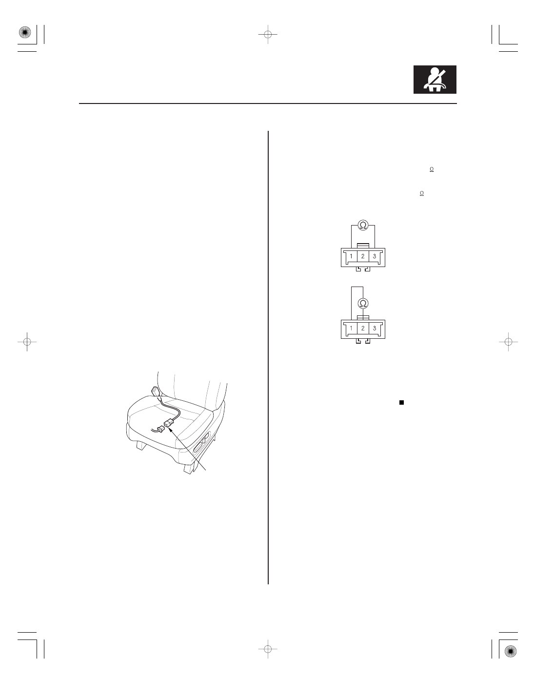
DRIVER’S SEAT BELT BUCKLE SWITCH
3P CONNECTOR
BLU
BLK
BLK
GRY
Open in Driver’s Seat Belt Buckle Switch
NOTE: Before doing this troubleshooting procedure,
review SRS Precautions and Procedures (see page
24-16) and General Troubleshooting Information
(see page 24-27).
1. Clear the DTC memory (see page 24-28).
2. Turn the ignition switch ON (II), then buckle and
unbuckle the driver’s seat belt several times.
3. Read the DTC (see page 24-27).
Go to step 4.
Intermittent failure, the system is OK at this
time. Go to Troubleshooting Intermittent Failures
(see page 24-29). If another DTC is indicated,
troubleshoot the DTC.
4. Turn the ignition switch OFF.
5. Disconnect the driver’s seat wire harness or floor
wire harness 3P connector from the driver’s seat
belt buckle switch 3P connector (A).
6. Buckle the driver’s seat belt.
• Measure the resistance between the No. 1 and
No. 3 terminals of the driver’s seat belt buckle
switch 3P connector. There should be 0
1
.
• Measure the resistance between the No. 1 and
No. 2 terminals of the same connector. There
should be an open circuit or at least 1 M
.
Go to step 7.
Replace the driver’s seat belt buckle assembly
(see page 24-6), then clear the DTC.
(cont’d)
Terminal side of male terminals
Terminal side of male terminals
Is DT C 61-1x indicated?
Ar e the r esistances as specif ied?