Honda Ridgeline. Manual - part 573
03
05
04
−
−
−
−
YES
NO
YES
NO
24-117
SRS UNIT CONNECTOR C (28P)
07SAZ-TB4011A
07YAZ-S3AA100
A
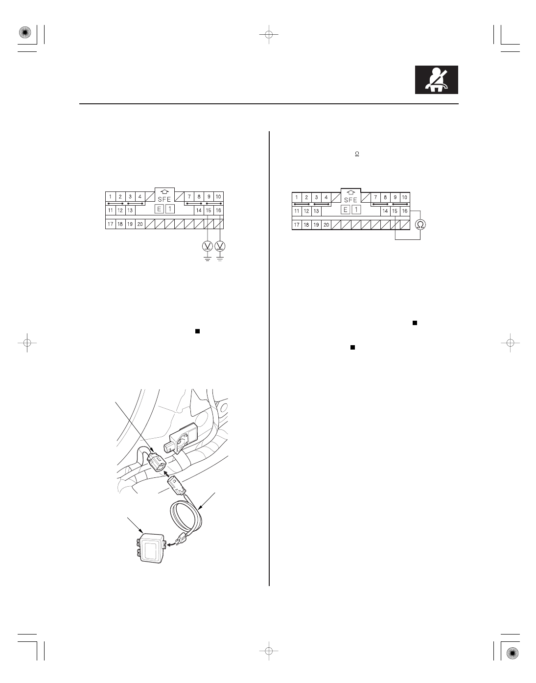
SRS UNIT CONNECTOR C (28P)
11. Measure the voltage between the No. 15 terminal
of SRS unit connector C (28P) and body ground,
and between the No. 16 terminal and body ground.
There should be 1 V or less.
Go to step 12.
Short to power in the floor wire harness;
replace the floor wire harness.
12. Turn the ignition switch OFF.
13. Connect the SRS inflator simulator (jumper
connector) and simulator lead H to the floor wire
harness 2P connector (A).
14. Measure the resistance between the No. 15 and
No. 16 terminals of SRS unit connector C (28P).
There should be 1.0
or less.
Faulty right side impact sensor (first) or SRS
unit; replace the right side impact sensor (first)
(see page 24-189). If the problem is still present,
replace the SRS unit (see page 24-188).
Open in the floor wire harness; replace the
floor wire harness.
Wire side of female terminals
Wire side of female terminals
Is the voltage as specif ied?
Is the r esistance as specif ied?