Honda Ridgeline. Manual - part 571
−
04
−
−
YES
NO
24-109
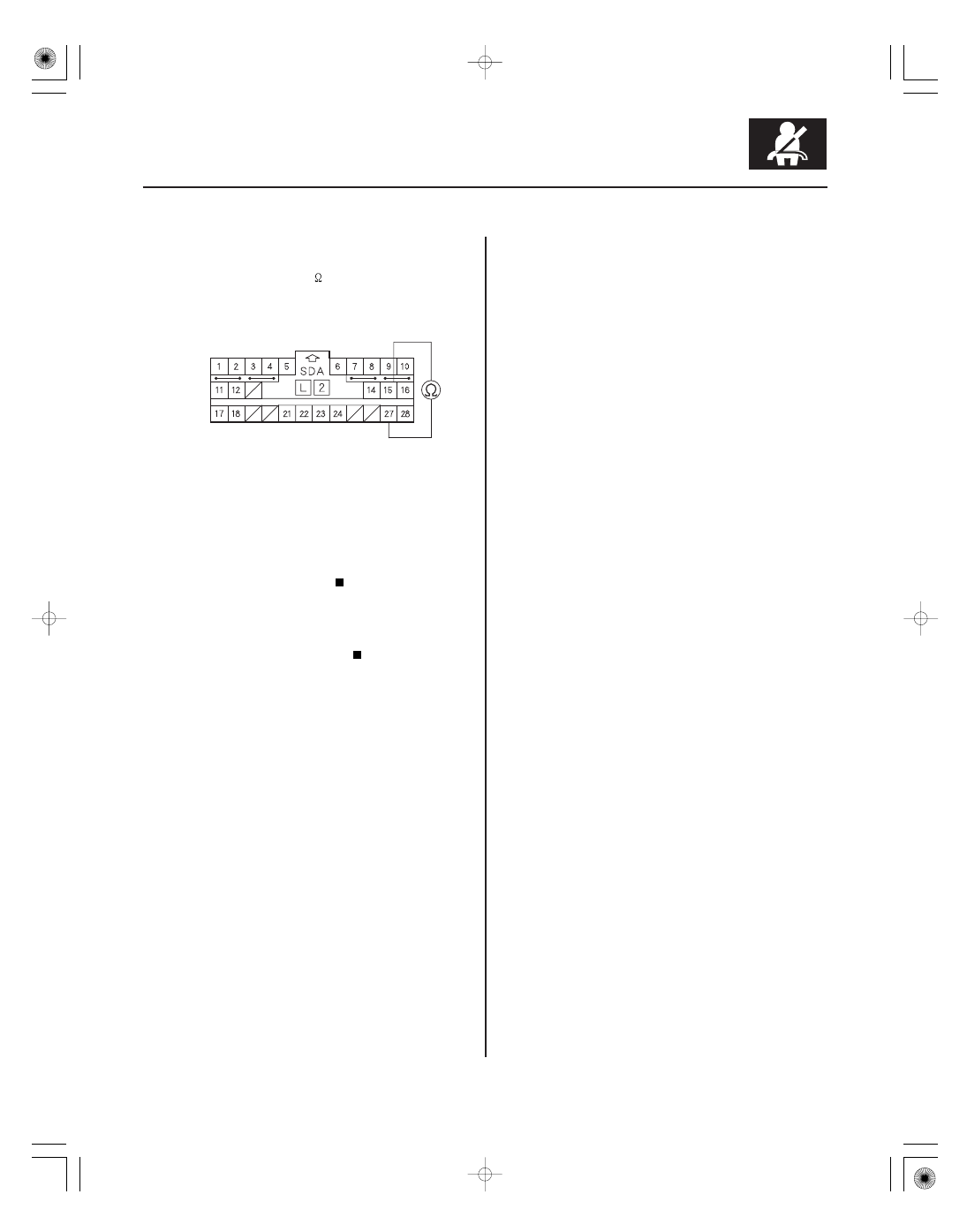
SRS UNIT CONNECTOR A (28P)
14. Measure the resistance between the No. 15 and
No. 27 terminals of SRS unit connector A (28P).
There should be 0
1.0
.
Faulty left front impact sensor or SRS unit;
replace the left front impact sensor (see page
24-193). If the problem is still present, replace the
SRS unit (see page 24-188).
Poor connection at C301, open in left engine
compartment wire harness, or open in dashboard
wire harness. Inspect C301 (see page 22-26). If it is
OK, replace the faulty harness.
Wire side of female terminals
Is the r esistance as specif ied?