Honda Ridgeline. Manual - part 554


  Index      Honda     Honda Ridgeline - service repair manual 2006-2008 year


Search            


Content   ..  552  553  554  555   ..


Honda Ridgeline. Manual - part 554


*01

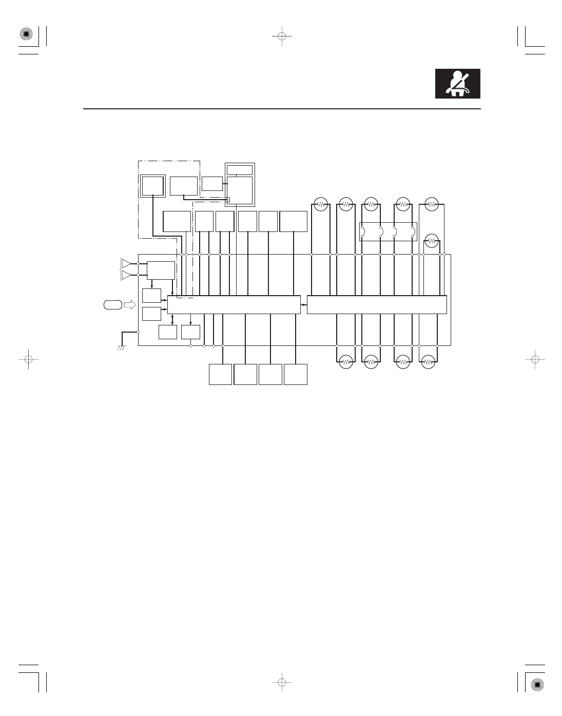
Self-diagnostic System

24-41

’07-08 models

DRIVER’S SEAT

IDC

MICROPROCESSOR and DIAGNOSTIC CIRCUIT

SRS UNIT

IMPACT

GND

TRIGGER CIRCUIT

SCS

MES

DLC

VA

VB

LEFT
FRONT
IMPACT
SENSOR

RIGHT
FRONT
IMPACT
SENSOR

SIDE
AIRBAG
INDICATOR

OPDS/ODS
UNIT

OPDS
SENSOR

FRONT
PASSENGER’S
SEAT

LEFT
SIDE
IMPACT
SENSOR
(FIRST)

RIGHT
SIDE
IMPACT
SENSOR
(FIRST)

DRIVER’S
SIDE
AIRBAG
INFLATOR

FRONT
PASSENGER’S
SIDE AIRBAG
INFLATOR

DRIVER’S
AIRBAG
FIRST
INFLATOR

DRIVER’S
AIRBAG
SECOND
INFLATOR

FRONT
PASSENGER’S
AIRBAG
SECOND
INFLATOR

FRONT
PASSENGER’S
AIRBAG
FIRST
INFLATOR

CABLE
REEL

FRONT
PASSENGER’S
SEAT BELT
TENSIONER

DRIVER’S
SEAT BELT
TENSIONER

RIGHT SIDE
CURTAIN
AIRBAG
INFLATOR

LEFT SIDE
CURTAIN
AIRBAG
INFLATOR

SRS
INDICATOR

DATA
LINK
CIRCUIT

MEMORY
CIRCUIT

SIDE
IMPACT
SENSOR

FRONT
IMPACT
SENSOR

UNDER
DASH
FUSE/
RELAY
BOX

POWER
SUPPLY
CIRCUIT

MULTIPLEX
INTEGRATED
CONTROL
UNIT

LEFT
SIDE IMPACT
SENSOR
(SECOND)

ROLL
RATE
SENSOR

RIGHT
SIDE IMPACT
SENSOR
(SECOND)

FRONT
PASSENGER’S
SEAT

FRONT
PASSENGER’S
WEIGHT
SENSORS

DRIVER’S
SEAT
POSITION
SENSOR

FRONT
PASSENGER’S
AIRBAG
CUTOFF
INDICATOR

A self-diagnostic circuit is built into the SRS unit; when the ignition switch is turned ON (II), the SRS indicator comes
on and goes off after about 6 seconds if the system is operating normally.
If the indicator does not come on, or does not go off after 6 seconds, or if it comes on while driving, it indicates an
abnormality in the system. The system must be inspected and repaired as soon as possible.

For better serviceability, the SRS unit memory stores a DTC that relates to the cause of the malfunction, and the unit is
connected to the data link connector (DLC). This information can be read with the HDS when it is connected to the DLC
(16P) (see page 24-27).

NOTE: Before you disconnect the negative cable from the battery for troubleshooting, make sure you have the anti-
theft code for the audio system and the navigation system (if equipped). Write down the XM audio presets (if
equipped).

(cont’d)


*02

SRS Unit Inputs and Outputs at Connector A (28P)

Terminal

Number

Wire Color

Terminal Name

Description

24-42

SRS

System Description (cont’d)

1

GRN/YEL

LA2

Power source for driver’s airbag second inflator

2

GRN/WHT

LA2

Ground for driver’s airbag second inflator

3

BLU/BLK

RA2

Power source for passenger’s airbag second inflator

4

BLU/RED

RA2

Ground for passenger’s airbag second inflator

5

LT GRN/BLK

MES

Memory erase signal input

6

BRN

SCS

Service check signal input

7

GRN/BLK

LA1

Power source for driver’s airbag first inflator

8

GRN/RED

LA1

Ground for driver’s airbag first inflator

9

YEL

RA1

Power source for passenger’s airbag first inflator

10

BLU/YEL

RA1

Ground for passenger’s airbag first inflator

11

PNK

SRS IND

SRS indicator output line

12

RED/BLU

PTT

Passenger’s airbag cutoff indicator output line

14

GRN/ORN

ODS/OPDS

Sends and receives communication signal

15

BRN/YEL

LFS

Ground for left front impact sensor

16

BRN

RFS

Ground for right front impact sensor

17

WHT

VA

SRS system sub power (common with ODS)

18

WHT/RED

VB

SRS dedicated power (dedicated booster circuit)

21

YEL

CDS

Crash detection signal

22

BLK

SRS GND A

Ground circuit for the SRS (G405)

23

BLK

SRS GND B

Ground circuit for the SRS (G405)

24

LT BLU

K-LINE

Sends and receives scan tool signal (serial data)

27

RED

LFS

Power source for left front impact sensor

28

GRN

RFS

Power source for right front impact sensor

NOTE:

BLU or BRN wire may be substituted for the wire colors in this table.

: ’07-08 Models

Wire side of female terminals


*03

SRS Unit Inputs and Outputs at Connector B (28P)

Terminal

Number

Wire Color

Terminal Name

Description

24-43

1

RED/BLU

LRP

Power source for driver’s side seat belt tensioner

2

RED/WHT

LRP

Ground for driver’s seat belt tensioner

3

RED/BLK

RRP

Power source for front passenger’s seat belt tensioner

4

RED/YEL

RRP

Ground for front passenger’s seat belt tensioner

5

GRN/WHT

SS

Ground for driver’s seat position sensor

6

BLU/RED

SS

Power source for driver’s seat position sensor

11

BLU/RED

LBSC

Driver’s seat belt buckle switch un-buckled signal

12

LT GRN

LBSO

Driver’s seat belt buckle switch buckled signal

15

BLU

RBSC

Front passenger’s seat belt buckle switch un-buckled signal

16

ORN

RBSO

Front passenger’s seat belt buckle switch buckled signal

NOTE:

BLU or BRN wire may be substituted for the wire colors in this table.

: ’07-08 Models

(cont’d)

Wire side of female terminals


*04

SRS Unit Inputs and Outputs at Connector C (28P)

Terminal

Number

Wire Color

Terminal Name

Description

24-44

SRS

System Description (cont’d)

1

WHT/GRN

LSA

Power source for driver’s side airbag inflator

2

WHT/RED

LSA

Ground for driver’s side airbag inflator

3

WHT/BLK

RSA

Power source for front passenger’s side airbag inflator

4

WHT/BLU

RSA

Ground for front passenger’s side airbag inflator

7

BLU/BLK

LCA

Power source for left side curtain airbag inflator

8

BLU

LCA

Ground for left side curtain airbag inflator

9

RED/YEL

RCA

Power source for right side curtain airbag inflator

10

RED

RCA

Ground for right side curtain airbag inflator

11

PNK/BLU

LBS1

Power source for left side impact sensor (first)

12

GRY/RED

LBS1

Ground for left side impact sensor (first)

13

GRN

RRS

Power source for roll rate sensor

14

BLU/GRN

RRS

Ground for roll rate sensor

15

BRN/YEL

RBS1

Power source for right side impact sensor (first)

16

LT GRN/RED

RBS1

Ground for right side impact sensor (first)

17

GRN/BLK

LSC1

Power source for left side impact sensor (second)

18

ORN

LSC1

Ground for left side impact sensor (second)

19

YEL/BLK

RCS1

Power source for right side impact sensor (second)

20

YEL

RCS1

Ground for right side impact sensor (second)

NOTE:

BLU or BRN wire may be substituted for the wire colors in this table.

Wire side of female terminals


Content   ..  552  553  554  555   ..