Honda Ridgeline. Manual - part 529
07
*03
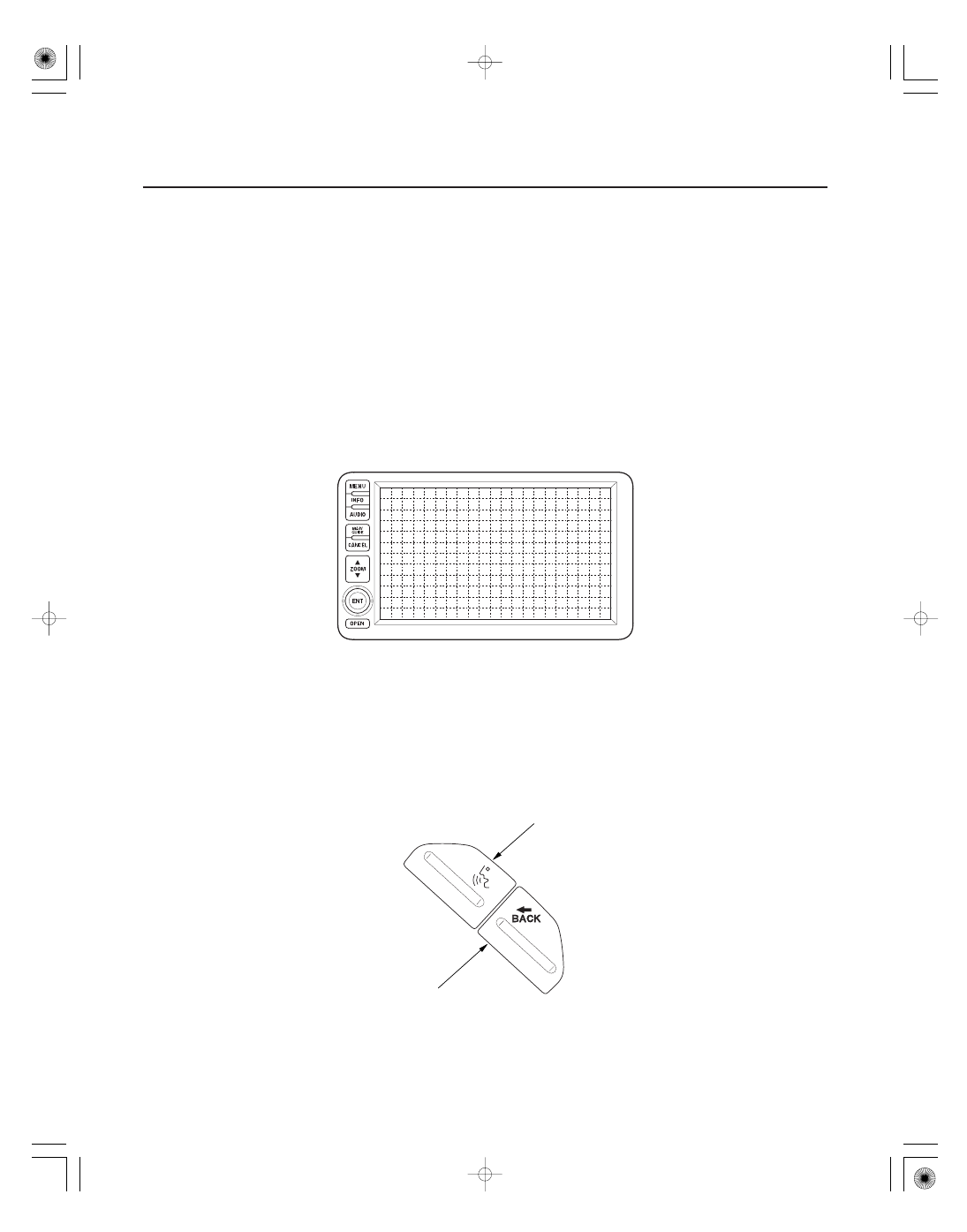
Audio Unit
Navigation Display
Microphone (MIC)
Talk Button
Back Button
23-82
Navigation System
System Description (cont’d)
NAVIGATION/VOICE CONTROL
TALK BUTTON
NAVIGATION/VOICE CONTROL
BACK BUTTON
The audio unit receives the audio driving instructions from the navigation unit and transmits the instructions through
the front speakers even when the audio system is in use.
NOTE: If the navigation volume is turned OFF, this feature is disabled.
The navigation display uses a liquid crystal display (LCD). The LCD is a 8-inch-diagonal, thin film transistor (TFT),
stripe type with 336,960 picture elements. The color film and fluorescent light are laid out on the back of the liquid
crystal film. The touch sensor on the front of the LCD consists of a touch sensitive resistive membrane with an infinite
number of possible touch locations. To maintain compatibility with earlier display units, the sensing locations are
confined to a grid of 20 vertical and 10 horizontal touch locations. This produces 200 total sensing zones. The
navigation display transmits the signal from each operation key and the touch switches to the navigation unit over the
GA-Net bus.
The microphone (on the ceiling, near the front map light) receives voice commands and transmits them to the
navigation unit for interpretation.
Activates the voice control system in the navigation unit to accept voice commands.
Returns the display to the previous screen (similar function as the CANCEL button).