Honda Ridgeline. Manual - part 501


  Index      Honda     Honda Ridgeline - service repair manual 2006-2008 year


Search            


Content   ..  499  500  501  502   ..


Honda Ridgeline. Manual - part 501


01

02

SJC8AGDJ46127037905FHAT00

01

02

SJC8AGDJ46127037903FEAT00

22-300

22-300

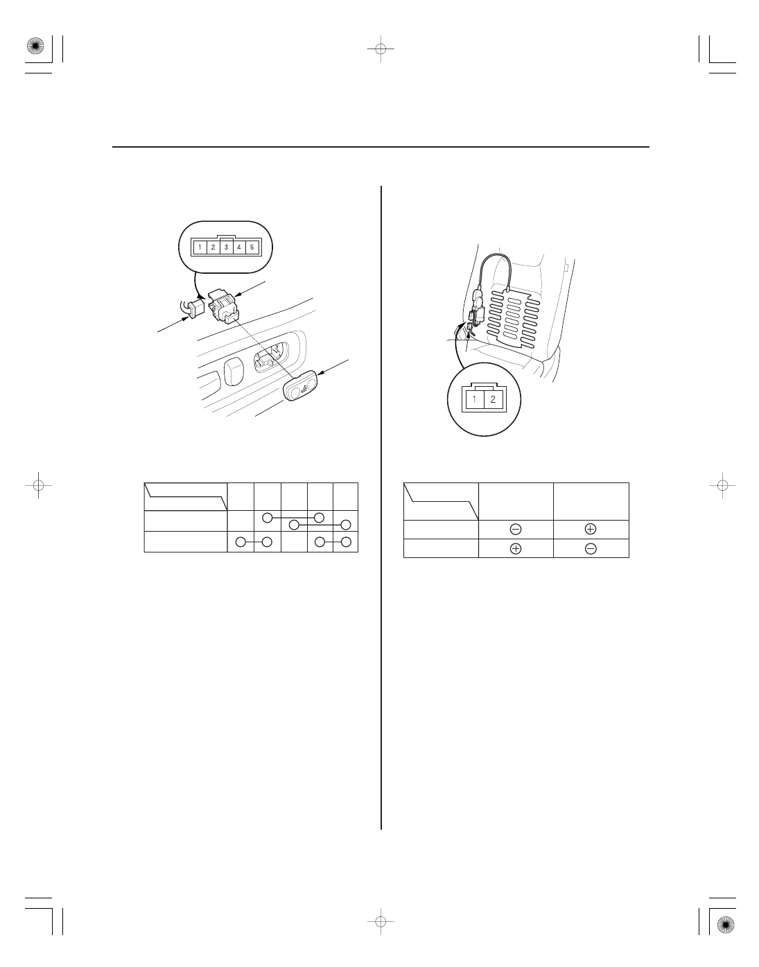
Power Lumbar Support

Switch Test/Replacement

Motor Test

A

B

C

Forward

Backward

Terminal

Position

1

2

3

4

5

A

Forward

Backward

Terminal

Position

1

2

1. Separate the lumbar support switch cover (A) from

the switch (B).

2. Disconnect the 5P connector (C) from the switch.

3. Check for continuity between the terminals in each

switch position according to the table.

4. If the continuity is not as specified, replace the

switch.

1. Remove the front seat (see page 20-97).

2. Disconnect the 2P connector (A) from the lumbar

support motor.

3. Test each motor by applying battery voltage and

body ground to the terminals.

4.

Terminal side of
male terminals

If the motor does not run or fails to run smoothly, replace
the lumbar support actuator (see page 20-110).

*01

SJC8A00J18573500000DAAT00

22-301

In-Bed Trunk Lid Opener

Component Location Index

IN-BED TRUNK LID
KEY CYLINDER SWITCH

IN-BED TRUNK LID
HANDLE SWITCH

IN-BED TRUNK LID ACTUATOR/LATCH SWITCH

TAILGATE SWITCH

IN-BED TRUNK LID MAIN SWITCH

MICU
(Built into the
under-dash fuse/relay box)

Test, page 22-150

Test, page 22-303
Replacement, page 22-303

Actuator Test, page 22-304
Latch Switch Test, page 22-180

Test, page 22-303
Replacement, page 22-303

*01

SJC8A00J18573500000EAAT00

22-302

In-Bed Trunk Lid Opener

Circuit Diagram

B4

A6

D6

G1

* : RTS, RTL, and EXL models

*

UNLOCK

BLK/YEL

1

2

Q4

G602

BLK

GRY/BLU

MICU

Q11

2

1

BLU/ORN

BLK

G602

UNDER DASH FUSE/RELAY BOX

Q12

G602

BLK

RED/BLU

1

2

Q7

3

BLU/YEL

2

1

1

2

F5

G601

BLK

RED/WHT

YEL/BLU

UNDER HOOD FUSE/RELAY BOX

No.23 (IG) (50 A)

No.22 (BAT) (120 A)

BATTERY

No.15 (40 A)

WHT

YEL

BAT

IG1

IGNITION SWITCH

BLK/YEL

No.21 (7.5 A)

No.7 (7.5 A)

No.8 (20 A)

UNDER DASH
FUSE/RELAY BOX

IG1 HOT in ON (II) and
START (III)

IN BED
TRUNK LID
ACTUATOR

IN BED
TRUNK LID
LATCH
SWITCH
(Closed :
Trunk lid open)

IN BED
TRUNK LID
ACTUATOR/
LATCH SWITCH

IN BED
TRUNK LID
MAIN
SWITCH
(Closed :
Switch ON)

IN BED
TRUNK LID
HANDLE
SWITCH
(Closed :
Switch ON)

IN BED
TRUNK LID
KEY
CYLINDER
SWITCH

TAILGATE
SWITCH
(Closed :
Tailgate
open)

01

SJC8A00J18573535281FHAT00

01

SJC8A00J18573535235FEAT00

22-303

22-303

Main Switch Test/Replacement

In-Bed Trunk Lid Handle Switch

A

B

A

B

1. Remove the glove box (see page 20-85).

2. Carefully push the main switch (A) out.

3. Disconnect the 2P connector (B) from the main

switch.

4. Check for continuity between the No. 1 and No. 2

terminals.

• With the main switch ON, there should be

continuity.

• With the main switch OFF, there should be no

continuity.

5. If the continuity check is not as specified, replace

the main switch.

1. Open the in-bed trunk lid, and remove the in-bed

trunk lid inner cover (see step 2 on page 20-187).

2. Disconnect the 2P connector (A) from the in-bed

trunk lid handle switch (B).

3. Check for continuity between the No. 1 and No. 2

terminal.

• With the handle pushed, there should be

continuity.

• With the handle released, there should be no

continuity.

4. If the continuity check is not as specified, replace

the switch (see page 20-188).

Test/Replacement


Content   ..  499  500  501  502   ..