Honda Ridgeline. Manual - part 498
*01
*02
SJC8AGDJ46170400000DAAT00
22-288
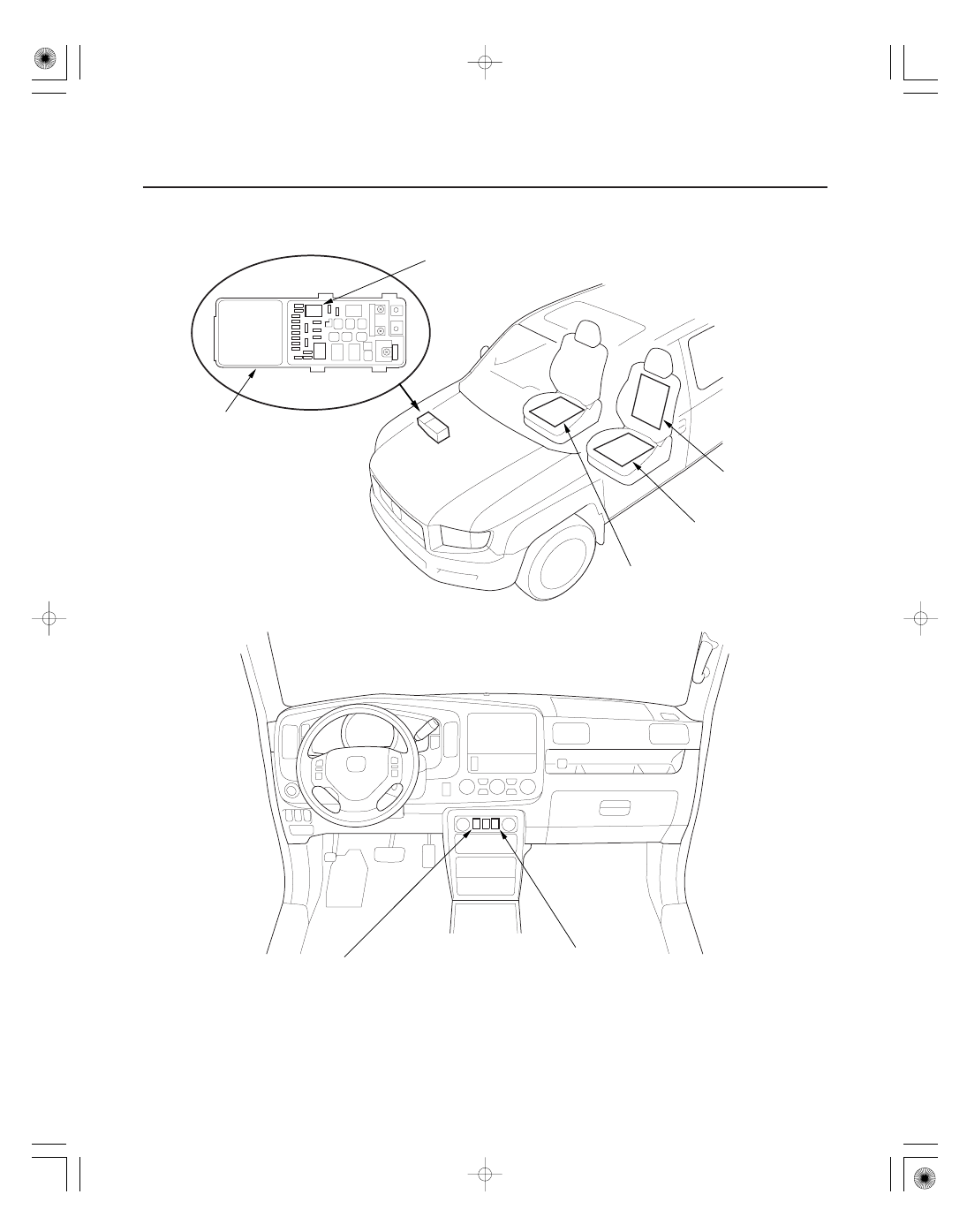
Seat Heaters
Component Location Index
UNDER-HOOD
FUSE/RELAY BOX/
RELAY CONTROL MODULE
SEAT HEATER RELAY
DRIVER’S SEAT-BACK
HEATER
FRONT PASSENGER’S
SEAT CUSHION HEATER
DRIVER’S SEAT
CUSHION HEATER
DRIVER’S SEAT HEATER SWITCH
FRONT PASSENGER’S
SEAT HEATER SWITCH
Test, page 22-75
Test, page 22-290
Test, page 22-290
Test, page 22-290
Test/Replacement, page 22-291
Test/Replacement, page 22-291