Honda Ridgeline. Manual - part 497


  Index      Honda     Honda Ridgeline - service repair manual 2006-2008 year


Search            


Content   ..  495  496  497  498   ..


Honda Ridgeline. Manual - part 497


*01

SJC8A00J46127000000DAAT55

22-284

Power Seats

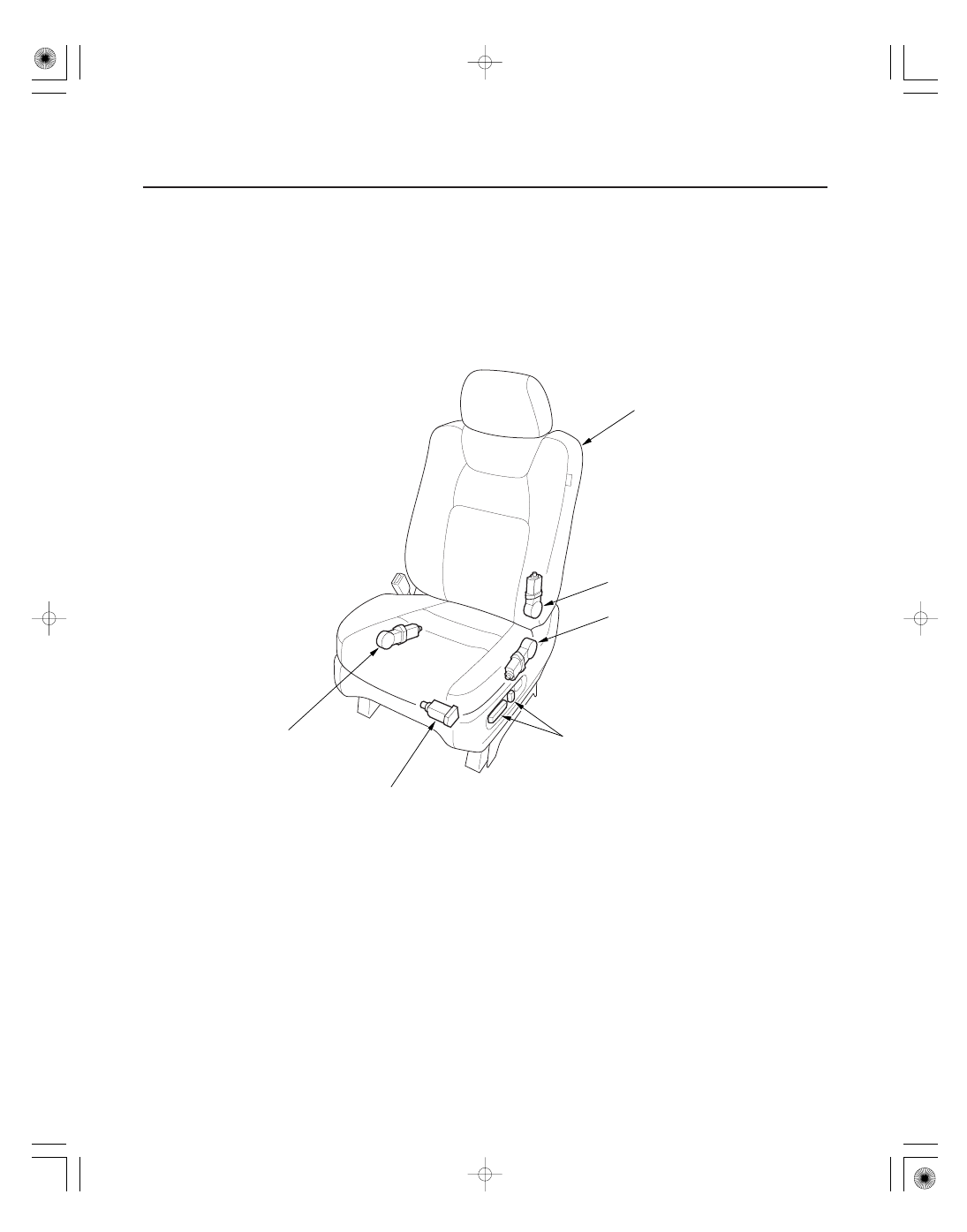
Component Location Index

DRIVER’S SEAT

FRONT UP-DOWN MOTOR

RECLINE MOTOR

REAR UP-DOWN MOTOR

POWER SEAT ADJUSTMENT SWITCH

SLIDE MOTOR

Test, page 22-287

Test, page 22-287

Test, page 22-287

Test/Replacement, page 22-286

Test, page 22-287

*01

SJC8A00J46127000000EAAT00

22-285

Circuit Diagram

B1

B6

BLK/YEL

F11

F13

G501

2

1

2

1

REAR UP DOWN MOTOR

RECLINE MOTOR

SLIDE MOTOR

FRONT UP DOWN MOTOR

2

1

2

1

4

WHT

6

YEL

12

BLU/ORN

1

ORN

5

YEL/RED

11

BRN

7

LT GRN

3

BLK

UP

DOWN

2

8

9

10

LT BLU

DRIVER’S POWER SEAT ADJUSTMENT SWITCH

DOWN

UP

BLU

WHT/RED

WHT/BLU

(20 A)

No.16

BLK

G501

No.14
(20 A)

No.22 (SEAT) (40 A)

BATTERY

UNDER DASH
FUSE/RELAY
BOX

BACK
WARD

FOR
WARD

FOR
WARD

BACK
WARD

UNDER HOOD
FUSE/RELAY BOX

01

02

SJC8A00J46127046701FHAT55

22-286

Power Seats

Power Seat Adjustment Switch Test/Replacement

B

A

Terminal

Position

SLIDE
SWITCH

RECLINE
SWITCH

FRONT
UP-DOWN
SWITCH

REAR
UP-DOWN
SWITCH

1

10

11

12

Forward

Backward

UP

DOWN

Forward

Backward

UP

DOWN

2

4

3

5

6

7

8

9

1. Remove the power seat adjustment switch knobs (A) and recline cover from the driver’s power seat (see step 7 on

page 20-101), then remove the two screws and the power seat adjustment switch (B).

2. Disconnect the 12P connector from the power seat adjustment switch.

3. Reinstall the adjustment switch knobs to the switch.

4. Check for continuity between the terminals in each switch position according to the table.

5. If the continuity is not as specified, replace the switch.

01

02

03

04

05

SJC8A00J46127046501FEAT55

Slide motor

Recline motor

Front up-down motor

Rear up-down motor

22-287

Motor Test

A

B

Forward

Backward

Terminal

Position

7

11

Forward

Backward

Terminal

Position

6

12

UP

DOWN

Terminal

Position

3

9

UP

DOWN

Terminal

Position

1

5

1. Remove the driver’s seat (see page 20-97).

2. Remove the power seat adjustment switch knobs

and recline cover from the seat (see step 7 on page
20-101).

3. Disconnect the 12P connector (A) from the power

seat adjustment switch (B).

4. Test each motor by applying battery voltage and

body ground to the 12P connector terminals.

5. If the motor does not run or fails to run smoothly,

check for an open in the driver’s seat wire harness
and recline motor subharness. If the harness is OK,
replace the motor.

• Recline motor (see page 20-103).
• Other motors:

– ’06 model (see page 20-108)
– ’07-08 models (see page 20-109)

Wire side of
female terminals


Content   ..  495  496  497  498   ..