Honda Ridgeline. Manual - part 487


  Index      Honda     Honda Ridgeline - service repair manual 2006-2008 year


Search            


Content   ..  485  486  487  488   ..


Honda Ridgeline. Manual - part 487


*01

SJC8A00J22100000000BBAT00

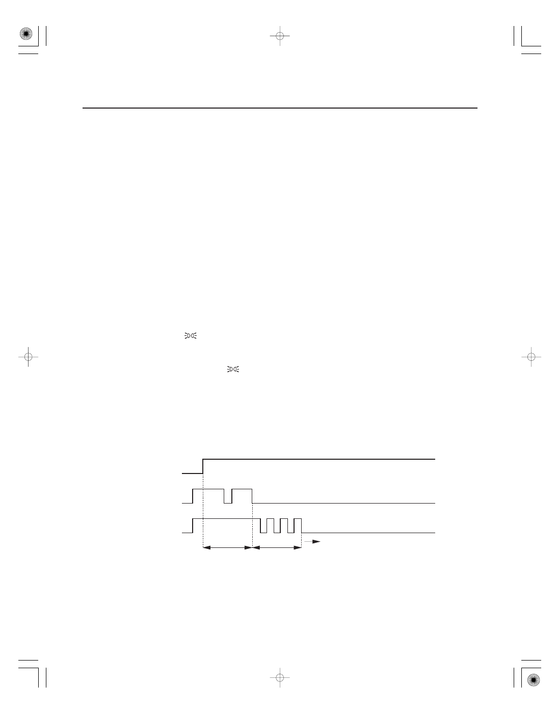
Entering the self-diagnostic function

22-244

Gauges

Self-diagnostic Function

OFF

ON(II)

OFF

ON

OFF

ON

Ignition
Switch

Lighting
Switch

Reset
Switch

5 sec.

Move to self-diagnostic mode.

5 sec.

Before troubleshooting the gauge system, refer to multiplex integrated control system B-CAN System Diagnosis Test
Mode A (see page 22-99).

The gauge control module has a self-diagnostic function shown.

• The beeper drive circuit check.
• The indicator drive circuit check.
• The switch input test.
• The LCD segments check.
• The gauges drive circuit check (Speedometer, Tachometer, Fuel gauge, Coolant temperature gauge).
• The communication line check (of the body-controller area network (B-CAN) communication line and the fast-

controller area network (F-CAN) communication line between the gauges).

NOTE:
Indicators are also controlled via the communication line.

Before doing the self-diagnostic function, check the No. 7 (7.5 A) fuse, the No. 21 (7.5 A) fuse and the No. 32 (7.5 A) in
the under-dash fuse/relay box.

1. Push and hold the RESET switch button.

2. Turn the lighting switch (

) ON.

3. Turn the ignition switch ON (II).

4. Within 5 sec., turn the lighting switch (

) OFF, then ON and OFF again.

5. Within 5 sec., release the RESET switch button, and then push and release the button three times repeatedly.

NOTE:

• While in the self-diagnostic mode, the dash lights brightness controller operates normally.
• While in the self-diagnostic mode, the RESET button is used to start the Beeper Drive Circuit Test and the Gauge

Drive Circuit Check.

• If the vehicle speed exceeds 1.2 mph (2 km/h) or the ignition switch is turned OFF, the self-diagnostic mode ends.

02

The Indicator Drive Circuit Check

Switch Input Check

The Beeper Drive Circuit Check

The LCD Segment Check

The Gauge Drive Circuit Check

22-245

OFF

ON

OFF

ON

OFF

ON

OFF

ON

Gauge needles

Beeper

5 sec.

Self-diagnostic
mode

Reset switch

When entering the self-diagnostic mode, the following indicators blink:
Seat belt indicators, charging system indicators, low fuel indicator, oil pressure indicator, high beam indicator, DRL
indicator (Canada models), VSA indicator, VSA activation indicator, brake system indicator, lights on indicator, A/T
gear position indicator, ABS indicator, cruise control indicator, mulfunction indicator lamp, in-bed trunk lid open
indicator, transmission fluid temperature indicator, TPMS indicator, D3 indicator, washer fluid level indicator, smart
maintenance indicator, back window open indicator and TPMS malfunction indicator.

After the intermittent beeper sounds at the initial stage of self-diagnostic, a beeper sounds continuously while any of
the following switch inputs are switched from OFF to ON:
Parking brake switch, VSA OFF switch, cruise control master, SET, RESUME, CANCEL switches, select switch, reset
switch, and dash lights brightness controller cancel switch.

When entering the self-diagnostic mode, the beeper sounds five times.

When entering the self-diagnostic mode, all the segments blink five times.

When entering the self-diagnostic mode, the speedometer, the tachometer, the fuel gauge, and the coolant
temperature gauge needles sweep from the minimum position to maximum position, then return to the minimum
position.

NOTE:
After the beeper stops sounding and the gauge needles return to the minimum position, pushing the reset switch
starts the Beeper Drive Circuit Check (one beep) and the Gauge Drive Circuit Check again.
The check cannot be started again until the gauge needles return to the minimum position.

If a needle fails to sweep or the beeper does not sound, replace the gauge control module.

(cont’d)

The needles sweep from the
minimum position to the
maximum position, then return
to the minimum position.

03

The Communication Line Check

Ending the self-diagnostic function

22-246

Gauges

Self-diagnostic Function (cont’d)

Normal:

Faulty (example Error 1):

While in the self-diagnostic mode, the Communication Line Check starts after the LCD Segments Check.
If all segments come on, the communication line is OK. If there is a communication line error, the word ‘‘Error’’ will be
indicated on the information display followed by a number.

• If the word ‘‘Error 1’’ is indicated, there is a malfunction in the communication line between the gauge control

module and the fast-controller area network (F-CAN). Check for DTCs in the PCM and troubleshoot any DTCs found.
If no DTCs are found, go to B-CAN System Diagnosis Test Mode A (see page 22-99).

• If the word ‘‘Error 2’’ is indicated, there is a malfunction in the communication line between the gauge control

module and the body-controller area network (B-CAN). Go to B-CAN System Diagnosis Test Mode A (see page
22-99). (B1155 to B1160).

• If the word ‘‘Error 3’’ is indicated, there is a malfunction in the communication line between the gauge control

module and the body-controller area network (B-CAN) and the fast-controller area network (F-CAN). Check for DTCs
in the PCM and troubleshoot any DTCs found. If no DTCs are found, go to B-CAN System Diagnosis Test Mode A
(see page 22-99).

If any communication line errors are found, go to B-CAN System Diagnosis Test Mode A (see page 22-99).

Turn the ignition switch OFF.
NOTE: If the vehicle speed exceeds 1.2 mph (2 km/h), the self-diagnostic function ends.

*01

SJC8A00J22100000000EAAT00

22-247

Circuit Diagram

BLK/YEL

A5

A6

B4

G1

D6

X35

N44

N36

E

D

C

B

A

CANCEL SWITCH

UNDER DASH FUSE/RELAY BOX

No.7 (7.5 A)

No.21 (7.5 A)

No.32 (7.5 A)

YEL

YEL

3

A8

A6

A5

A4

A3

6

1

WHT/GRN

WHT/BLU

LT BLU

G402

BLK

2

RED

RED/BLK

5

SELECT

RESET

BLU/BLK

BLU/WHT

3

6

5

4

2

RED/BLK

1

RED

YEL

A2

YEL/RED

WHT/BLK

IG1

BAT

ACC

BEEPER

WHT/RED

A19

DRIVE CIRCUIT

No.15 (40 A)

No.22 (BAT) (120 A)

GAUGE CONTROL MODULE

A20

POWER SUPPLY CIRCUIT/CONTROLLER AREA NETWORK CONTROLLER

FUEL GAUGE

SPEEDOMETER

YEL

WHT

BLK/YEL

YEL

No.23 (IG) (50 A)

UNDER HOOD FUSE/RELAY BOX

BATTERY

IGNITION SWITCH

TACHOMETER

IG1 HOT in ON (II) and
START (III)
ACC HOT in ACC (I)
and ON (II)

COOLANT
TEMPERATURE
GAUGE

HIGH BEAM
INDICATOR (LED)

CANCEL
SWITCH

LIGHT
(0.56 W)

No.21 (7.5 A) FUSE
(UNDER DASH
FUSE/RELAY BOX)

LIGHT
(0.84 W)

DASH LIGHTS
BRIGHTNESS
CONTROLLER
(In the gauge
control module)

SELECT/
RESET
SWITCH

DASH LIGHTS BRIGHTNESS
CONTROLLER

DASH LIGHTS
BRIGHTNESS
CONTROLLER
(In the gauge
control module)

LCD
DISPLAY

No.4 (15 A) FUSE
(UNDER HOOD
FUSE/RELAY BOX)

No.4 (15 A) FUSE
(UNDER HOOD
FUSE/RELAY BOX)

1

1

(cont’d)


Content   ..  485  486  487  488   ..